Continue to Site

Welcome to EDAboard.com

Welcome to our site! EDAboard.com is an international Electronics Discussion Forum focused on EDA software, circuits, schematics, books, theory, papers, asic, pld, 8051, DSP, Network, RF, Analog Design, PCB, Service Manuals... and a whole lot more! To participate you need to register. Registration is free. Click here to register now.

3 Phase Induction Motor - Overload Protection Relay

Status
Not open for further replies.

Shanmukesh

Newbie level 6
Joined
Nov 25, 2014
Messages
12
Helped
3
Reputation
6
Reaction score
3
Trophy points
3
Activity points
86
Brief Introduction of the project:
Three phase induction motor overload protection relay using a microcontroller based circuit.

Parameters being Monitored by Microcontroller:
Three phase current consumed by the motor.

Parameters known:
Motor's rated current
Service factor
Locked rotor current of motor
Locked rotor withstand time.

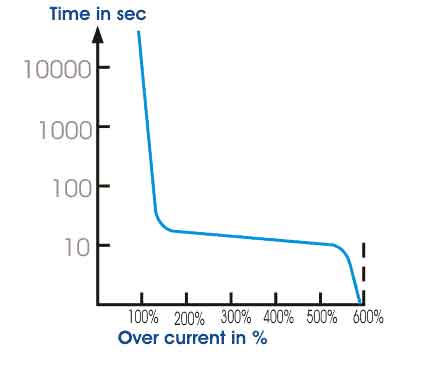
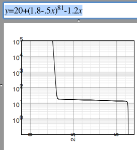
How do I set the Overload curve or response curve of the relay? (Current v/s time)

The probable solution can be, by implementing a lookup table.

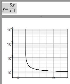
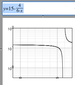
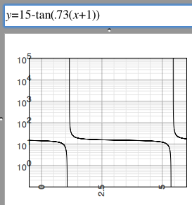
but what would be the Equation of the curve so that it can be calculated in run-time.
 

Three phase induction motor

Not that I'm a motor expert...

1.

Your protection system will have a timer. You'll start it counting whenever it senses current draw reaching an alert level.

After a second or two current may fall back to a safe level. Then you'll cancel the alert and reset the timer.

However if current stays higher than the alert level, then the time count continues for a preset number of seconds, at which time it disconnects the relay.

2.

It is typical for motors to draw surge current on startup. The amount can be 3x or 4x the running level (possibly more if the load is attached).

Your protection system can ignore this surge if it lasts for the first 1 or 2 seconds of operation.

3.

Do you attach and detach loads while the motor runs? Your protection system should allow for a current surge at such times.

4.

In electronics we have the common advice to design with a 100 percent margin for safety.

Locked rotor... If yours is similar to other motors, then it draws extreme current. Suppose it draws 10A. Then set your alarm level to trigger at 5A. Start a timer.

Withstand time... Suppose this is 8 seconds. Then set your timer to wait 4 seconds. Then it disconnects the relay.

5.

Design the protection system so it needs manual reset. In particular, once the relay disconnects, it should not connect automatically under any circumstances, even if current falls to zero. The danger is that
the motor might start running unexpectedly while you're working around it.
 
Every motor has a thermal limit curve.
For E.g.
4020861800_1417060579.jpg


If the current at any particular instance exceeds the value as of in the thermal limit curve, then motor starts heating up. Even 10 deg rise in temp above the rated value decreases the life of coil insulation by half.
Hence, this should be avoided.

Therefore, the trip characteristics of Motor protection relay should be just below the Thermal limit curve.

Now, coming back to the point of concern.
The microcontroller should continuously monitor the time and current consumed by the motor.
Whenever the current at particular instance exceeds the curve the relay should trip.
To do this, the microcontroller should continuously calculate max current allowed at time 't'
So, there must be equation between the time 't' and allowable current 'i'
 

The limit curve shows the corner points for implementation of an overload protection. The algorithm should be however a thermal model, instantaneous winding power dissipation I²R filtered by one or multiple low pass filters compared to a programmable threshold value.
 
The algorithm should be however a thermal model

I completely agree FvM that thermal model algorithm will be the more accurate and reliable.
But, A product designed using Thermal model algorithm will have to prompt for many datas from the user like:
- Specific heat capacity of motor
- Running heat dissipation factor
- electrical resistance
- hot stall time
- cold stall time
- cooling time constant etc etc etc.
depending on this parameters i can continuously compute TCU (thermal capacity used). Once the TCU has reached 100% the relay shall trip and wait till the motor cools down.
This would be an advance application. It can be called as motor management system.

But, I want to design a simpler and less sophisticated device that can be used even by a non-technical person.
The device will just have a knob to set the time for which the Startup high current is allowed.

Based on this time, the curve will be deduced or calculate.
 

Thermal relays are used to protect small induction motors from locked rotor.

Additional thermal sensing in built into large 500 Hp motor bearings which if seized will burn out faster than windings so this is used to protect motor against sleeve bearing failures.
 

In terms of the math, your graph resembles two reciprocal equations.

It is exactly as I expected. Each and every point on the graph is matching my requirement just by playing around with the multiplier. Thank you for the equation :thumbsup:

Prior to posting in this forum I was trying to frame equation using Natural Log. It was just making my calculations complicated. But this was so simple that my execution time would be reduced dramatically.

One thing I would like to know that what was your approach to think in the right direction and arrive to the correct equation. Because what I was doing is completely incorrect.
 

One can also create a power series for 3 zones for
I<=130% . . . . . t = 1e5 * I^-30
130% < I <540% . t = 20 * I^-1.01
I >=540% . . . . . . . etc

The graph does not give initial conditions however.

The limit for starting surge should be different for cold start from a hot start where it has been running at 90~100% all day. i.e. or the number of start/stops per minute.

Whereas an insulated thermal sensor might driven by current sensing to model the heat mass might be more accurate.

Otherwise dwell times between unsuccessful starts from worn bearings must be programmed that trip the 600% current, often going to 800% for a stalled rotor.
 
The curve for allowable overcurrent versus time is a simplified description of the protection relay. It only corresponds to the actual behaviour for the special case that the current is constant during the overload event.

In the generally case the current is not constant and the curve or a respective equation is useless to decide when to disconnect the motor. You need an algorithm that integrates I²dt to handle all possible current versus time waveforms.
 

I was trying to frame equation using Natural Log. It was just making my calculations complicated. But this was so simple that my execution time would be reduced dramatically.

One thing I would like to know that what was your approach to think in the right direction and arrive to the correct equation. Because what I was doing is completely incorrect.

I had some practice when I tried to fashion a simple equation to simulate the diode V/I curve.

The upward-going line approaches 100%, but never quite reaches it. It's an asymtote. Asymtotes are characteristic of reciprocal equations. Hence the form 1/x.

The sideways-going line at 12 seconds also resembles an asymtote.

-----------------------------

As it turns out, the tangent equation is a way to re-create your entire graph. Juggle a few coefficients and...

4406496500_1417201628.png


This equation does not reflect anything about motor dynamics, of course. It's just a mathematical curiosity.

Another all-in-one equation which works is:

5913991500_1417197591.png
 
Breaker, Breaker, do you read me.

**broken link removed**
( addressing USA readers, but similar references exist for IEC Stds.)

There has been some confusion in the past years concerning the application of motor controllers. UL508A addresses this issue as to what devices make up a motor controller and what kind of options are available.

The combination motor controller is a device or combination of devices designed to start and stop a motor by making and breaking the motor current.

The controller is capable of interrupting the locked-rotor current of the motor. In the United States, the National Fire Protection Association (NFPA) 70, National Electrical Code (NEC), Article 430 addresses motors, branch-circuit protection, motor overload protection, control circuits, motor controllers, conductors, the combination of these devices and how they relate to one another in regards to protection and sizing.

The combination motor controller generally consists of a circuit disconnecting means; motor branch-circuit, short-circuit and ground-fault protection device; a magnetic or solid state motor controller; and overload relay. The circuit disconnecting means, motor branch-circuit, short-circuit and ground-fault protection device, usually consists of a fusible disconnect or a circuit breaker. The circuit breaker can be either an instantaneous trip or inverse time breaker.

- The instantaneous trip breaker provides short circuit protection where the inverse
time breaker provides both short circuit protection and overload protection.


- The magnetic motor controller is generally referred to as a contactor.
- The motor controller makes or breaks the motor current.
- The overload relay provides protection from overload conditions.
- Auxiliary pilot devices such as push-buttons and selector switches, whether mounted on the unit or mounted remotely, are used to energize or de-energize the motor controller.
- Pilot lights are used to show equipment status. A typical combination motor controller using a contactor and overload relay

...

In recent years, UL added the Type E combination motor controller to its list of combination motor controllers in section 508, Industrial Control Equipment. The Type E controller is a manual self-protected combination motor controller that provides both overload and short-circuit protection in a compact device. This design DOES NOT require an upstream circuit breaker or fuses. The Type E controllers are designed to have a disconnect means, branch circuit protection, motor control and motor overload is a single device, the same features required on a combination motor controller


motor trip.png

breaker.png

The important think to remember is there are many causes of overload, the worst being an insulation breakdown after a stalled motor or worn rotor with an arc that results in a short circuit across the line with follow-on damage sometimes called "ENERGY LET-THRU".

 
Status
Not open for further replies.

Part and Inventory Search

Welcome to EDABoard.com

Sponsor

Back
Top