Continue to Site

Welcome to EDAboard.com

Welcome to our site! EDAboard.com is an international Electronics Discussion Forum focused on EDA software, circuits, schematics, books, theory, papers, asic, pld, 8051, DSP, Network, RF, Analog Design, PCB, Service Manuals... and a whole lot more! To participate you need to register. Registration is free. Click here to register now.

3 Phase Half Bridge Driver Protection Components

Status
Not open for further replies.

ata90

Member level 5
Joined
Apr 13, 2009
Messages
89
Helped
1
Reputation
2
Reaction score
1
Trophy points
1,288
Activity points
1,945
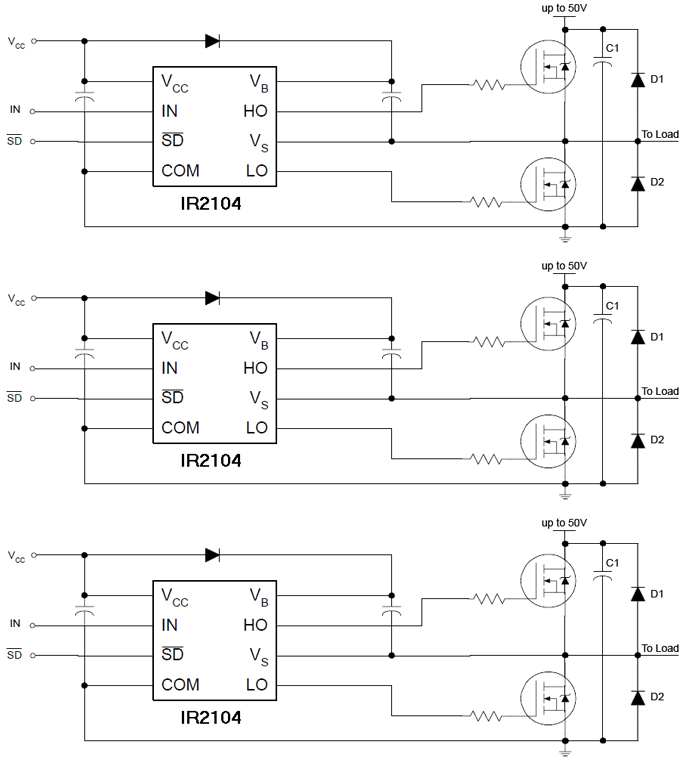
Below, you can see schematic of 3 Phase Half Bridge Driver. Diode D1 & D2 are protection components.


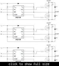
1) should I add some other components in order to increase protection reliability (I mean Protection of the MOSFETS)?
2) How should I choose C1 and D1 (which parameters and factors should I consider for choosing these components) ?
 

Diodes Dx are connected in parallel to the MOSFET internal substrate diodes and not generally required. Bus voltage bypass capacitors are however strongly recommended.

In some cases, fast free-wheeling diodes are added to the bridge output stage. This mainly works with schottky diodes, that have a lower forward voltage than the substrate diodes. But preferably, a H-bridge would be controlled to achieve synchronous switching, so the output current is never carried by a diode.
 

Thanks for your advice.

Refer to **broken link removed** page 6, Designer place six diodes 1N5408 parallel to MOSFETS.

1) So, do you mean I replace Dx with schottky diodes? what are the characteristics of your preferred schottky diodes?
2) Do not further components need for increasing protecting of the MOSFETs (I heard MOSFETs are so sensitive and fail if we don't use them properly)?
3) what capacitance should I use as Bus voltage bypass capacitors?
 

1N5408 is a slow rectifier diode and won't serve a purpose in parallel to a MOSFET.

If you look sharp at the said schematic diagram, you'll notice, that "Phase A" on the left side most likely means the mains input and "Phase A" on the right the inverter output.

For high voltage operation, you won't find suitable schottky diodes.

Bus bypass capacitors should be in a several 100 nF up to uF range, mounted close to the MOSFETs.
 

2) Do not further components need for increasing protecting of the MOSFETs (I heard MOSFETs are so sensitive and fail if we don't use them properly)?
3) what capacitance should I use as Bus voltage bypass capacitors?

Any ideas about these 2 questions?
 

You can use autoprotect mosfet.

In short-break the IRF have a applications that uses the voltage peak of the MOSFET when stop driving for protect the mosfet against high current.

My English is not so good but I hope you can understand, if you want I can put the circuit in my site.


Edson
 

Thank you Edson.
let me know your site and your desired circuit.
 

**broken link removed**

Here is the circut. Use the translate for english (bellow the page).
Edson
 

While I was surfing websites, I encounter to a device which named TVS diode. it will be placed parallel with protected device such as MOSFET. it has schematic similar to ZENER diode. does anyone know something about it?
 

Status
Not open for further replies.

Similar threads

Part and Inventory Search

Welcome to EDABoard.com

Sponsor

Back
Top