Continue to Site

Welcome to EDAboard.com

Welcome to our site! EDAboard.com is an international Electronics Discussion Forum focused on EDA software, circuits, schematics, books, theory, papers, asic, pld, 8051, DSP, Network, RF, Analog Design, PCB, Service Manuals... and a whole lot more! To participate you need to register. Registration is free. Click here to register now.

3-Phase AC motor control help required

Status
Not open for further replies.

abicash

Member level 3
Joined
Jun 26, 2007
Messages
60
Helped
1
Reputation
2
Reaction score
1
Trophy points
1,288
Activity points
1,772
Hello

I have already designed a PWM based 3-phase sine generator .
PWM freq = 16KHZ

The bridge stage is 3 nos Dual IGBT modules with 10000uf/600v electrolytic capacitor across the input to the bridge and 3 nos 0.22uf/600v capacitors across each module.

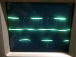
I have attached the waveform across R-Y phases and i see a lot of oscillations on the scope.
On looking closely i see this to be the effect of BEMF from the AC motor.

I request someone to comment on this.Maybe pointers or desirably a solution.
Please help
 

Attachments

  • Motorwf.jpg
    Motorwf.jpg
    74.2 KB · Views: 82

Shame there are no time divisions on the CRO. I think it is just capacitive pick up of the PWM from the other phases. What is the rating of the motor and how long are the leads to it? What I am thinking is that as one half of an output stage goes on, the current rises exponentially until that half output goes off, the back EMF then rises until that half output comes on again where the current rises (or falls) to a different level, that half output then goes off and more back EMF might be generated. The back EMF = L X dI/dT, as L stays the same, the back EMF should then follow the level of the current which it does not.?? If it is back EMF, it will come from a high impedance source, try putting a resistor across each phase, say 10 K, should be enough to severely damp out any back EMF induced oscillations.
Frank
 

Dear Frank
Thanks for replying.
I will answer your doubts asunder

1)The waveform is seen on a CRO since surprisingly the oscillation doesn't show up on a DSO.The frequency which you see is a 30Hz envelope by a 8KHz PWM sine
2)The rating of the motor is 1HP and the leads are quite long (close to 15 meters).

I got another control card which generates 3-phases with the older Triangular-sine comparison method (whereas i have generated a Look up table method). On this control card i do not see this kind of waveform.
Although methods are different , i have done the exact same algorithm to generate 3 phases.
On a Lamp load i see no oscillations (i am refraining from calling that BEMF).
When i switch it to the motor do i see this, so i am now compelled to call it BEMF.

EDIT: added 10k as suggested...no change!
 
Last edited:

So the problem is with your "look up table" PWM? On an engineering forum, I have read that some motors when driven with PWM get so much induced currents running around them that their bearings can fail as they are conducting this induced current to earth, so a proper carbon brush + slip ring has to be installed to earth the spurious currents. I was thinking on the line of this spurious current was being induced in "the other" windings and producing this funny effect. As the 10K had no effect its not just a bit of capacitive coupling through a few hundred Pf of interwinding capacitance, which would of course reject the LF and accentuate the HF.
So when your H bridge has just switched off after pumping some current into a winding in one direction, the other half comes on for a micro (nano?)sec and pumps current in the other direction? Are you sure of your timing of reading out your ROM look up?
It would be worth while to try and synchronise your CRO on one PWM pulse to see what and where the spurii are. It is interesting that they seem so change across the LF half cycle and are not related to the instantaneous current that is being pumped into the winding.
Frank
 

No comment about the photo in post #1. It's just unreadable.

I notice that you don't tell about any unwanted effects with the motor drive, e.g. speed fluctuations, unexpected noise. Are there any objective problems at all?

By design, a H-bridge clamps "back EMF" of inductive loads to the DC bus. But the detail behaviour depends also on the applied modulation scheme, which (along with many other design facts) hasn't been mentioned yet.

The load capacitance of 15 m cable definitely matters. I can well imagine how the interferences generated by the respective current peaks spread over to the control circuit and cause a lot of problems if the circuit layout is less than perfect.
 

Dear Frank and FvM
Thanks for replying.

The 3 half bridges are driven by a 360° sine look up table(LUT) of 32 variables.The first half bridge starts at the 0th position in LUT , the second half bridge starts at the 11th and the last starts at 22nd positions in the LUT respectively.

I have 6 channel PWM out on the Microcontroller .Each vertical limb works in complementary (top and bottom IGBTs) and there is a dead time of 4us.The PWM freq is 8KHz.

Regarding problems, i find none visible problems.I am just speculating from the observed waveform that it might create a problem if a more powerful motor were driven, since i presumed that what i see is a BEMF waveform.

So when your H bridge has just switched off after pumping some current into a winding in one direction, the other half comes on for a micro (nano?)sec and pumps current in the other direction? Are you sure of your timing of reading out your ROM look up?

I am very sure that there is no latency in reading the LUT. Moreover when i connect a purely resistive load of 3 nos delta connected lamps, i see a very clean waveform. But i think you might be right where you say that "the other half comes on"
 

You may want to monitor the motor voltage after passing a RC low-pass, showing the actual flux generating voltage.

In fact I won't exclude that there's a problem in your inverter operation, but it can't be identified from a badly triggered analog scope waveform.
 

Status
Not open for further replies.

Similar threads

Part and Inventory Search

Welcome to EDABoard.com

Sponsor

Back
Top