ELECTRONICIENSENIOR
Member level 3
Hello, I am french so I may write with faults
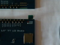
I am trying to use this display :

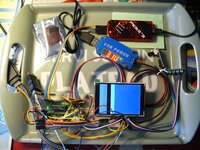
But I do not use the Arduino world, the target is to make a handheld device to display ECG with an AD8232.
So I don't use libraries, I expectwriting all in C for a Microchip PIC16 mid range.
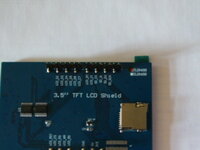
I have bought several items, all in 8bits data bus, not SPI, for speed.
The blue FR4 versions have 5v and 3v3 pins on connector, but 3v3 is not wired to AMS1117 reg.
So I have shorted in and out to supply 3v3 via 5v pin.
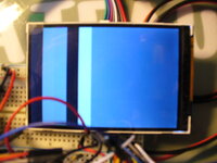
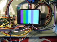
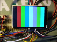
Even in whoel reset the screen is white, and a deffect for one which has two cyan zones !
I have not set pwm values, not driven display ON, so I expected it should be black. And the memory write for 5000 pixels is not visible.
May I have help ?
Best regards

I am trying to use this display :
3.5'' TFT Full Color Module 480x320 LCD Mega2560 Shield with/without Touch | eBay
Les meilleures offres pour 3.5'' TFT Full Color Module 480x320 LCD Mega2560 Shield with/without Touch sont sur eBay â Comparez les prix et les spécificités des produits neufs et d'occasion â Pleins d'articles en livraison gratuite!
www.ebay.fr
But I do not use the Arduino world, the target is to make a handheld device to display ECG with an AD8232.
So I don't use libraries, I expectwriting all in C for a Microchip PIC16 mid range.
I have bought several items, all in 8bits data bus, not SPI, for speed.
The blue FR4 versions have 5v and 3v3 pins on connector, but 3v3 is not wired to AMS1117 reg.
So I have shorted in and out to supply 3v3 via 5v pin.
Even in whoel reset the screen is white, and a deffect for one which has two cyan zones !
I have not set pwm values, not driven display ON, so I expected it should be black. And the memory write for 5000 pixels is not visible.
May I have help ?
Best regards