Continue to Site

Welcome to EDAboard.com

Welcome to our site! EDAboard.com is an international Electronics Discussion Forum focused on EDA software, circuits, schematics, books, theory, papers, asic, pld, 8051, DSP, Network, RF, Analog Design, PCB, Service Manuals... and a whole lot more! To participate you need to register. Registration is free. Click here to register now.

3.3V to 12V DC Boost Converter ?

Status
Not open for further replies.

cybero

Newbie level 3
Joined
Apr 12, 2015
Messages
3
Helped
0
Reputation
0
Reaction score
0
Trophy points
1
Activity points
32
Hello everyone,

I'm working with a microcontroller which its supply voltage range is 1.8V to 3.6V
I want to connect a solenoid to this mcu (this solenoid will be activated occasionally).

Current–voltage characteristic of the solenoid:

Input voltage: DC12V
Direct current: around 400mA

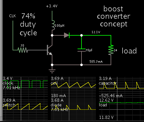
So, my idea is to connect a 3.6V or 3.3V battery to the mcu and use a DC DC Boost Converter to supply the solenoid.

But the problem is that I cannot find any 3.6V to 12V DC DC converter which can also gives 0.5A.

Any help would be really appreciated.
 

A Solenoid is like a linear motor with large inrush during motion dependant on the load and may be 5~10x the steady state current determined by coil resistance, Rs.

A suitable design uses a power source that is matched or exceeds the requirements of the load inrush current and time duration.

A step-up converter also raises source impedance rapidly which defeats the purpose.

I suggest you rethink your power requirements and define them more accurately and choose a power source with much lower source impedance (<10%) than the effective inertial load during surge.
(f=ma , force and plunger depth is used to determine pulse duration and power required with low loss in source.

This means your power source ESR should be <10% of the coil Rs. Preferably <5%.
Power Source ESR is measured by drop in voltage for rise in current. ratio.
 

Hi,

the switch ON current looks like this:
solenoid.jpg
(http://www.tdsjp.co.jp/english/techno/note.html)

You see the intermediate current drop while the core is moving.

There is no peak during switch ON.


*********

There are a lot of IC manufacturers for step_up / boost converters.
one of them is linear technology.
They have an online product selector tool, Other manufacturers also.
http://www.linear.com/products/Step-Up_(Boost)_Regulators

12V/400mA means 4.8W. with an efficiency of 80% (for example) you need an input current of 1.8A at 3.3V.

Klaus
 
  • Like
Reactions: cybero

    cybero

    Points: 2
    Helpful Answer Positive Rating
I agree but if L/R time constant is short compared to plunger time, the 1st hump has a sharp rise time to Imax determined by V/Rs.

Normally current is reduced after latching when power is minimum after motion is completed.

Reducing power is required to maintain holding force as the rated current in the solenoid is much less than the peak current.
I rated = W_rated / V_rated which can be managed by small duty factors or reduced driver current state when latched.
 

Hi,

coming into my mind:

if you use a buck converter IC with enable input, then you could use this to switch ON/OFF the solenoid.

Good point of SunnySkyguy to reduce power after solenoid is activated. Saves power and heat.
With a buck converter and some R and C at the feedback this could be done automatically.

Klaus
 

My suggestion is to remove the winding from your solenoid and rewind it with twice diameter wire as many turns as you can fit in. Operate it from the battery.
Don't worry about inrush current; solenoid is an inductor, when you switch it on the current is zero and then it rumps up.
 

I have one point to make about this setup.

When you boost a voltage from 3V3 to 12V at 400mA, you need at least 2A from the 3V3 source/battery, and more for peak current.

Depending on the type of battery you use for the 3V3 source, you will have a problem drawing that much current from battery. Even if you get that kind of current, the battery may suffer, and the life expectancy will be reduced.

I would have used a 12V source supplying the circuit, and made the MCU 3V3 power from that voltage with a small DC-DC switcher.

I'm going to have this circuit working 24/7 during some years and the solenoid is going to be activated just twice a day maximum during a few seconds.
So if I have to lose energy, it must be just when using the solenoide, not during all the time.
 

Gorgon,
They sell amplifiers of 1500W that work on 12V car battery. They also sell converters that produce 4000W 220VAC from your car battery. We have 3.6V battery and 12V solenoid, the task is to find 5W converter, almost as easy as finding Cinderella by the shoe.
 

I'm going to have this circuit working 24/7 during some years and the solenoid is going to be activated just twice a day maximum during a few seconds.
So if I have to lose energy, it must be just when using the solenoide, not during all the time.

Ok, why not making a separate 12V supply/battery for the solenoid then, and keep the 3V3 for the controller. If your system is running 24/7 I suppose you have some sort of charge solution for the battery in question? What is the Ah rate of your 3V3 battery, and what is the nominal supply current for the controller?
 

Ok, why not making a separate 12V supply/battery for the solenoid then, and keep the 3V3 for the controller. If your system is running 24/7 I suppose you have some sort of charge solution for the battery in question? What is the Ah rate of your 3V3 battery, and what is the nominal supply current for the controller?

It does not have any charge solution for the battery, just have to replace it.

I will use a high capacity battery, something >6 Ah

I don't have any controller, why do you think I need a controller ?
 

Batteries give you a lot of flexibility in terms of your voltage/capacity because you can stack cells in series or parallel.

In your application, there is a strong case to be made for 3 cells in series giving you 12V. This can direct drive the solenoid and easily handle the surge there. Then you can efficiently and cheaply step down to 3.3V with any number of off-the-shelf DC-DC's.
 

In case this helps in making decisions or designs, this is a simple boost converter simulation.

3.4V stepped up to 12V at 500 mA.


A load should always be kept connected, or the output voltage will soar.

By interleaving two or more of the above converter, you can draw a more steady current from the battery.
 

It does not have any charge solution for the battery, just have to replace it.


I don't have any controller, why do you think I need a controller ?


Only your first post saying that, but what do I know :D
 

An LT1271 should be able to do what you want.
It is a 4 Amp Switching Regulator.
(4 Amp Maximum Input)
 

Status
Not open for further replies.

Similar threads

Part and Inventory Search

Welcome to EDABoard.com

Sponsor

Back
Top