Continue to Site

Welcome to EDAboard.com

Welcome to our site! EDAboard.com is an international Electronics Discussion Forum focused on EDA software, circuits, schematics, books, theory, papers, asic, pld, 8051, DSP, Network, RF, Analog Design, PCB, Service Manuals... and a whole lot more! To participate you need to register. Registration is free. Click here to register now.

2N3055 performance problems

Status
Not open for further replies.
saturation base current 2n3055

I don't know why semiconductor manufactures have such a wide range of specs for the 2N3055 transistor. Typical ones and better are very good. Weak ones should be re-labelled as garbage.

Maybe the manufacturers hope that designers like me use enough in parallel so that the circuit still works with all weak ones.

I am not naive.
I designed and built many circuits in my career. A few went into production and tens of thousands were made. Not a single one ever failed because my design used worst case spec's.
 

2n3055 transistors in parallel

The current discussion is very much usefull for me and let me mention the fact that I took this schematic from an old book of indian origin. The actual circuit that I uploaded carries some mistakes that had to be corrected before it is brought into reallity like the power supply connections of 7473 etc. and I think that there must be more issues addressed carelessly. But all these things are very good from learning point of view. A perfect circuit never offers you much opportunities to learn prolem rectification. Using this circuit I am glad to learning a lot from you people.

As suggested by FvM, I changed 150 ohm resistor with 33 ohm (that actually was 44 ohm when measured) and I found an increase in current flow from battery. But there is a considerable voltage drop at transformer input. :cry: 
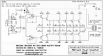
Following is the data

Load = 200 Watt Tungsten Bulb
Battery Voltage=12V
Current draw from battery = 16.5 A
Voltage at 12v Winding (on either end) = 10V (expected 12V)
Current draw at each side of 12V winding= 8A
Output Voltage = 230 Volts (at 280 volt winding)

when load was increased by adding a fan
Battery Voltage=12V
Current draw from battery = 25 A
Voltage at 12v Winding (across both ends) = 8.5V
Current draw at each side of 12V winding= 12.4A
Output Voltage = 200 Volts (at 280 volt winding)

By changing the resistance value current withdrawl has increased but there is a considerable voltage drop. I remember there had been around 11.75V with 150ohm resistance.


Also during battery charging through mains the transformer outpouts 12V-0-12V but after rectification 11V is available to charge battery.

intersting... :D

what you suggest:?:

Added after 19 minutes:

Look at the attached circuit. It differs only in oscillator and the power stage still use same transistors and same design with the claim to give 500W out put from two pairs of 2N3055.
 

resistor na base do 2n3055

The corrections to the 500W inverter that I made (4 pairs of 2N3055 transistors and many other improvements) were messed up recently by MP the moderator. My corrected version had people say it worked well and was posted there for almost 4 years.

MP's version needs matched 2N3055 transistors, its output is about 250W max, its oscillator resistor value is much too low (the datasheet says a minimum of 10 times higher), its oscillator capacitor value is much too high, it doesn't have any voltage spike protection diodes and it uses two quad opamps instead if a single dual opamp.

A 500W square-wave inverter that has transistors uses about 600W from a 12V battery. Then each side must conduct 600W/12V= 50A. The 2N3055 transistors have a max current rating of 15A and perform poorly at 10A and above. They will obviously blow up at 25A each.
 

branchement cd4047

4 pairs of 2N3055 transistors
Indeed, that's absolutely necessary for 500W. A threefold darlington circuit reduces efficiency with 12V supply, unfortunately. But it's an effective way to deal with unknown 2N3055 current gains.

Unbelievable, that the MP corrected version ever run with nominal load.

@maijaz99: please consider that a usual car battery won't supply 50A without considerable voltage drop.
 

2n3055 gain specifications

Can you send me the correced 500W inverter that you made having 4 pairs of 2N3055 transistors with other improvements, Audioguru:D.
 

inverter circuits using 2n3055

My corrected inverter is here. Ronnie in The Philippines made a few and drew my schematic.
It uses old fashioned and lossy 2N3055 transistors because they were available there and Mosfets were not available.
 

Attachments

  • 500w_inverter_final_8724.png
    500w_inverter_final_8724.png
    201.1 KB · Views: 72

inverter con 2n3055

Thanks Audioguru but Ronnei missed power rating of 100 ohm resistor and the values of resistors at pin 10 and 11 of CD4047.

Added after 3 minutes:

Another point is the transformer is 10V-0V-10V rating that can be used for step up OK but if u need to use the same for 12V battery charging, its simply unpedictable.
 

2n3055 resistance

maijaz99 said:
Thanks Audioguru but Ronnei missed power rating of 100 ohm resistor.
They are rated fot 1/4W. They have a max voltage of 3V across them for half the time so their max average dissipation is only 90mW.

and the values of resistors at pin 10 and 11 of CD4047.
The minimum input resistance of the opamp is about 1M so a resistor value from a dead short to about 100k will work fine. The circuit used 4.7k resistors.

Another point is the transformer is 10V-0V-10V rating that can be used for step up OK but if u need to use the same for 12V battery charging, its simply unpedictable.
A 10v transformer makes a rectified and filtered 12.3V which is too low to charge a 12v lead-acid battery. 13.8vDC is needed.

The inverter circuit uses antique parts so it has a lot of voltage loss. Then it works better with a 10V transformer.
 

2n3055 circuit application 12v 10a

Its the resistor 100 ohm on main supply voltage (nea zener diode). I suppose a 100 ohm 10W would work fine? the rest is clear now :D
 

irfz44 heater

Oh. You mean the 100 ohm resistor at the zener diode?
It dissipates power only during brief voltage spikes. Use a half watt resistor.
 

parallel 2n3055

Thanks a lot and I shall report after trying it. I shall use my 12V-0-12V transformer and hope to get good results.
 

2n3055 driver circuit

Hi audioguru,

I made changes to my circuit according to your provided schematic. I forgot to place 100ohm quarter watt resistance between emitter of 2n3055 and ground. When connected to battery the circuit started producing a sharp noise typical of 2N3055. The heat sink and a pair of power transistors on both sides got too too much hot to touch (the trnasistors have been mounted on heat sink with conductive paste). I doubt they are functional anymore. This is with out any load at 220V side. What u suggest will it be corrected by incorporating 100ohm resistance or there is something else going on.
 

databook transistor 2n 3771

The 100 ohm resistors turn off the output transistors quickly. Your output transistors on one side were still turned on when the other side turned on so the output transistos got fried.
 

2n3055 datasheet in a 12vdc power supply circuit

I have observed a variation in 0.1ohm 10W wire wound resistor value. What do u suggest should I use ready made or wind myself using nichrome wire.
 

how to connect two 2n3055 in parallel

Hi audioguru,

I built inverter according to your schematic. Following are observations

- It immediately burnt one pair of power transistors. Due to that the rest of transistors were getting extremely hot.

- After replacement all the transistors worked under normal temperature but the output is low.

- When 200 watt tungsten bulb was attached, ac voltage at transformer input dropped from 23.7V to 19V and when a fan was added voltage further dropped to 15V. The output was 197 volt ac after stepup.

- transistors on one side stopped working when operated at no load. Afterwards there was no output at load of 100W tungsten bulb.

It appears that this circuit too is giving less than 200W output with three pairs of 2N3055 transistors in power output stage.

why there is so considerable voltage drop (9V)? What you suggest.

M. A. Ijaz
 

2n3055 workhorse

The simple circuit uses old transistors instead of modern Mosfets. The output and driver transistors have a saturation voltage loss of up to 3V and the emitter resistors have a voltage loss of up to 1.25V.

Maybe your defective transistors are fake ones.

The output is a square-wave that cannot be measured with an ordinary voltmeter.
 

2n3055 max current

The issue here is the history of the 2N3055 and limitations of JEDIC specification system at the time.

The 2N3055 was introduced as one of the first inexpensive silicon (NPN) power transistors, homitaxial (grown junction) transistors. It was slow, soft saturation, but rugged. At only 800KHz GBw it exhibited virtually no second breakdown and could run DC close to 2 amps at 60V if you could keep the junction temperature down.

Because it didn't show second breakdown that was never specified independently when RCA introduced it in the early 1960s.

The number became almost mythical. I've even seen MOSFETs numbered 3055 to draw on its reputation. Its shortcommings became evident in the design of linear regulators. Other vendors made planer versions with 2.5 to 4 MHz GBw and much lower Vce sat. Secon breakdown on thes comence at 40Vce and DC rating drops to 100mA at Vce equal 60V. Not the same device at all BUT they met the JEDIC registered specifications. It led to decades of confusion with RCA and the other originators trying to get an alpha suffix to designate one or the other to no avail.

Later devices introductions were carefull to hard specify second breaksown to avoid this issue.

:!:
 

Status
Not open for further replies.

Similar threads

Part and Inventory Search

Welcome to EDABoard.com

Sponsor

Back
Top