Continue to Site

Welcome to EDAboard.com

Welcome to our site! EDAboard.com is an international Electronics Discussion Forum focused on EDA software, circuits, schematics, books, theory, papers, asic, pld, 8051, DSP, Network, RF, Analog Design, PCB, Service Manuals... and a whole lot more! To participate you need to register. Registration is free. Click here to register now.

reading ac voltage through microcontroller pic16f887 for stabilizer

Status
Not open for further replies.

jit_singh_tara

Full Member level 6
Joined
Dec 22, 2006
Messages
325
Helped
9
Reputation
18
Reaction score
4
Trophy points
1,298
Location
Delhi , India
Activity points
4,293
dear friends ,
PLease suggest how to measure ac voltage for stabilizer application....need to instantly switch transformer tapping when voltage drops.

I tried to convert 220v ac to around 12 v ac ...using transformer....then i rectified it with the full wave rectifier...then i used potential divider to bring it to 5v for adc ...and then i had to put a big cap to remove ripples....
But by doing so my response to change in input voltage becomes very slow ....as voltage across changes slowly.....
But if i remove the cap , the voltage is not pure dc as it was converted to full wave rectified .
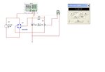
ckt.JPG


What should be done in order to measure ac voltage for stabilizer application.any practical ckt or idea is welcome..........

thx
 

you can use a sine wave mapping for your case, but I feel like thats going to take more number of instruction cycles on your controller. I think you should check how these SMPS controller ICs work. That will give you a very good idea about the implementation. They use a threshold voltage and a resister devider for an input and using comparators swich on and off the pwm.
To start with you can check UC3845
 

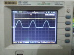
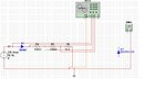
I am able to read the ac voltage by clipping the lower cycle and using resistor divider to scale the 300Vac to Round 5 v positive half cycle peak......
ac voltage clipping and reducing amplitude.JPG

20130925_081611.jpg...


Now i am able to read the peak of this cycle after sensing the interrupt on zero crossing :i.e the moment i detect a high at transistor bc547 collector...i start taking samples and read the peak of readings in upper half cycle....Now i am instantly able to read the voltage ......

By using other method of converting the ac to dc using a cap to filter the wave ,decreased the response time.....which could not be used in stabilizer....coz i have to switch the relay in the very next cycle of detecting the fluctuating ac voltage .....


now the sensing part is fine . but i m facing problem in switching the relay 25A 24V dc Relay.I am trying to switch it as follows :
1. there is a tapping from the autotransformer which is around 18v ac , which i am using for two purposes :
a. Driving my mcu card which senses voltage and displays it on seven segment ,does the processing for switching relays .
b. Using the same supply and converting it to 24V dc using a diode bridge and 1000uf cap 35V .for driving the uln2003 for relays....

The moment the relays switches on and off i face problem as:
a. There is spike on my mcu card 5V power supply....
b. in some cases when a relay switched for switching higher winding tapping of the autotransformer , The mcu card stops working the display gets stuck ,,all the relays show 0V across them and there is humming in the auto transformer .

PLease suggest what to do for this........
 

hello,


Could you synchronise the commande of relay to zero volt detection of the AC voltage measure ?
to avoid spike on coil of relais
and add some RC filter(snubber) across the contact ie: 0,1µF + 1K.

and maybe use a full bridge of diodes instead one 1N4007 to get double alternance measure...
 

how can i remove the spike on the 5V supply ......when the relay switches the tapping of transformer.......here is the image......
NewFile0.jpg

I am using 24V relay with reverse 1n4007 diode across the coil of the relay.....
relay.jpg

i am using 5 such relays ....every time the relay switches a winding of the transformer ...there is a spike on the 5V line ....what should i do......
 

The voltage measurement doesn't look real.

Apparently you have connected your circuit ground to mains neutral (using autotransformer for uC supply). I wonder how you can measure voltages with a regular oscilloscope in this situation?
 

Can't you use a 12V transformerless powersupply and convert 12 V AC to DC and scale it to 5V DC then filter it and feed it to ADC? In code calibrate so that it shows Vrms AC or Vm AC value.
 

hello,

Try to use intermediate relay wich need low energy to give a dry contact ,
and drive your 24V relay outside , to remove the spike energy far away of the MCU.

Do you have a load on your 24V relay ?..
maybe need also (snubberç RC circuit accross the contact .
 

Status
Not open for further replies.

Similar threads

Part and Inventory Search

Welcome to EDABoard.com

Sponsor

Back
Top