Welcome to our site! EDAboard.com is an international Electronics Discussion Forum focused on EDA software, circuits, schematics, books, theory, papers, asic, pld, 8051, DSP, Network, RF, Analog Design, PCB, Service Manuals... and a whole lot more! To participate you need to register. Registration is free. Click here to register now.
For isolation and safety, you should use a transformer-based power supply instead of building a non-isolated 220V to 12V converter, especially considering that the power requirement is 72W.
Maybe you don't want to use transformer because of the large size of the 50Hz transformer. In that case, you should be using SMPS circuits. But, even they will (should) be transformer-isolated. Just, the ferrite transformer will be very small.
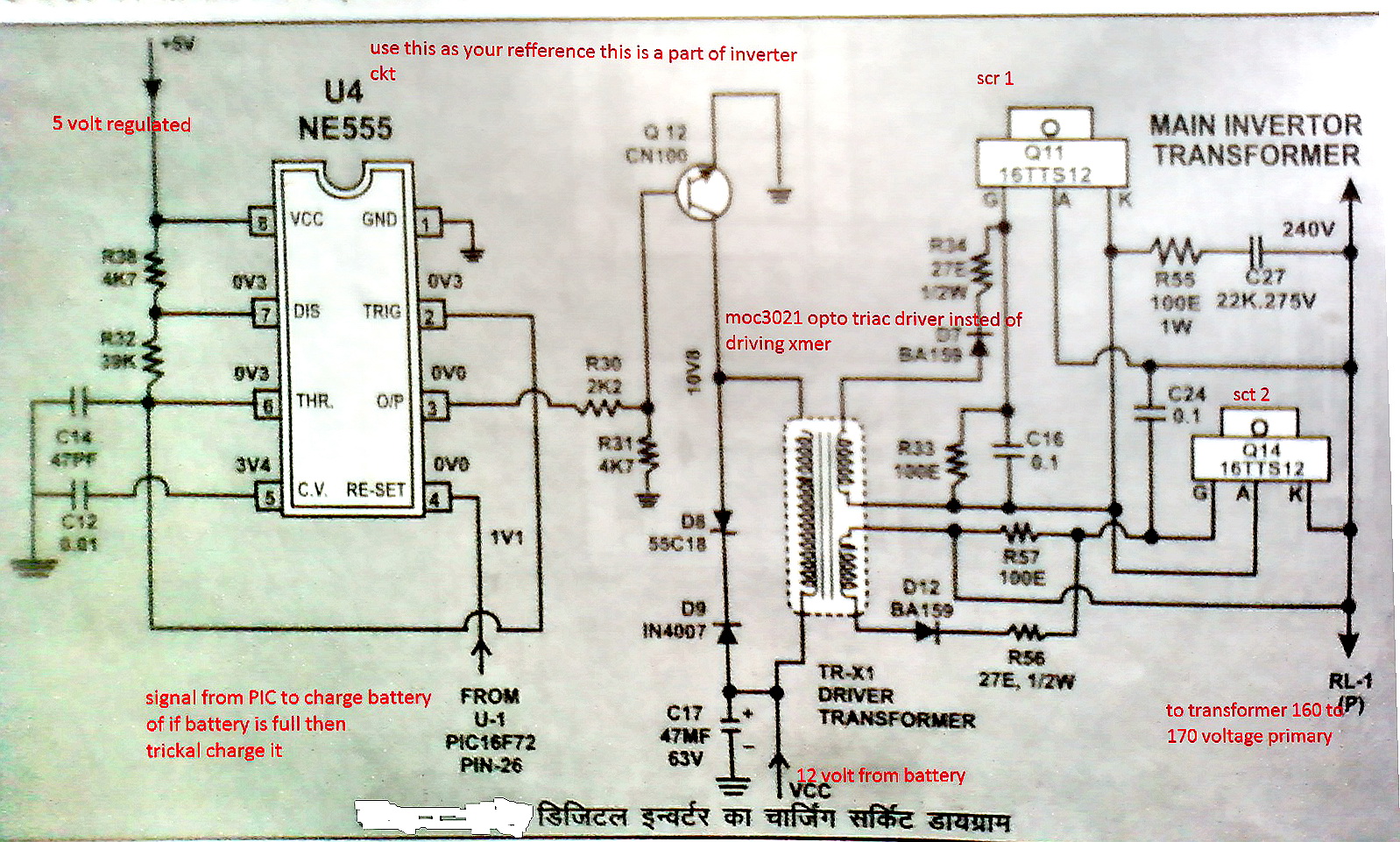
Actually i want to make a charger of 12v 6a rating .
in which I used triac to drop the 220V 60hz supply at 12 or 15V. and then filter out the 12V
To control the triac i wanna use PWM by IC555.
It's better you use a transformer along with the triac or use SMPS circuits.
Since this is for a battery charger, isolation is a must. Otherwise, upon touching a battery terminal, you'll receive a nasty shock. This is not allowable for battery chargers, especially if the battery is not sealed inside a box or case.
You can use a transformer rated at 120V or 140V primary. Then, you can decrease the voltage around that level to control output voltage and thus current.
If you use SMPS, you can use a flyback, forward or half-bridge offline converter.
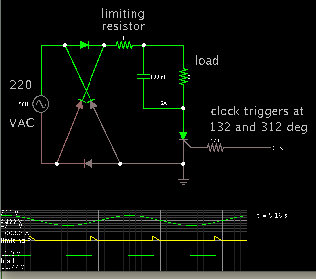
It is true this concept is used in controlling AC devices. So I made a simulation to see whether it could power a high current DC load.
This diagram is about the same as what you are describing:
The 'clock' is a substitute for circuitry that is adjusted to trigger at particular moments in the incoming mains cycle.
Some kind of limiting resistance is needed. Notice the 100 amp bursts going through the circuit, even with a limiting resistance. It would require components that are robust, rated to withstand this much power.
The capacitor will have 100 amps going through it. You would need a large bank of capacitors to split the load.
If your current needs were smaller, this could become a workable idea.
And it is a high voltage risk, since it is in direct contact with house voltage. So this method is not recommended.
Some of the resistance would be in the house wiring, and in the fuse.
In fact my schematic above is likely to blow a fuse.
Whatever the amount of resistance, there will still be massive current going through every component.
I only put together the simulation in order to demonstrate how it might theoretically be done.
However such a project is too risky to undertake. If it didn't blow a fuse, it could result in components exploding, and/or personal injury.
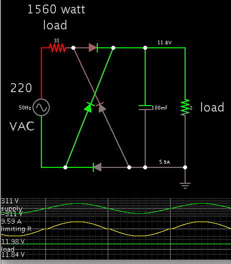
In the name of theoretical interest, here is a more practical method. You must install a heavy load inline. 1560 watts. 31 ohms. This could be a number of lamps in parallel. Maybe a vacuum cleaner. It would create a lot of inconvenience.
This method makes the scr/triac network unnecessary.
This site uses cookies to help personalise content, tailor your experience and to keep you logged in if you register.
By continuing to use this site, you are consenting to our use of cookies.