Continue to Site

Welcome to EDAboard.com

Welcome to our site! EDAboard.com is an international Electronics Discussion Forum focused on EDA software, circuits, schematics, books, theory, papers, asic, pld, 8051, DSP, Network, RF, Analog Design, PCB, Service Manuals... and a whole lot more! To participate you need to register. Registration is free. Click here to register now.

S11 and gain relation

Status
Not open for further replies.

falguni_raval

Newbie level 3
Joined
Oct 11, 2012
Messages
4
Helped
0
Reputation
0
Reaction score
0
Trophy points
1,281
Activity points
1,333
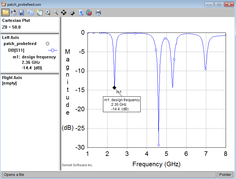
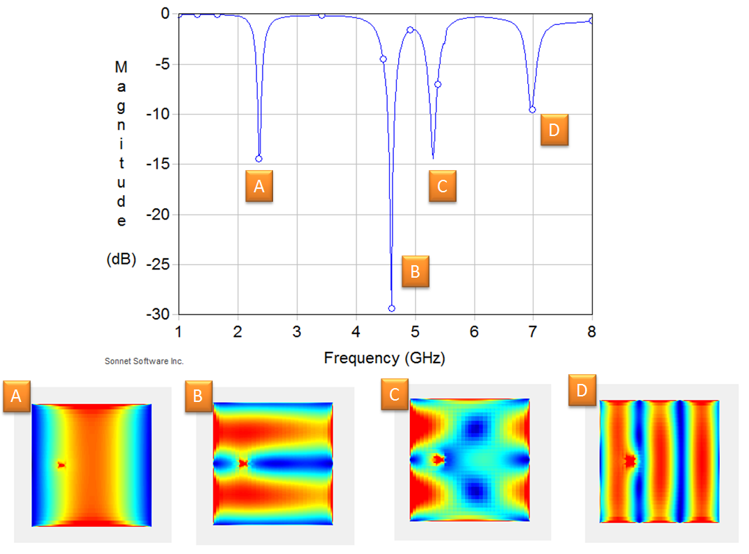
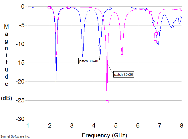
I have simulated patch antenna at 2.65 GHz in hfss. I am getting S11 less than -10 db at 2.65 GHZ, 4.88GHZ and 6.88 but when i look at the gain associated with those freq. I get gain at 3.33 db at 2.65 GHZ. But at 4.88GHZ and 6.88 GHZ ,i am getting gain in minus.what can be the reason for that?Are these freq. called harmonics? FR4 is used as substrate.

what is the standard gain of patch antenna when FR4 is used?
 

what is the standard gain of patch antenna when FR4 is used?

Not very high, around 3 dBi

Are you saying there's 3 dips in the return loss? There ideally should only be 1 for a basic patch. Can you upload a picture of your antenna layout?
 

Are you saying there's 3 dips in the return loss? There ideally should only be 1 for a basic patch.

If you look high enough in frequency, there will be more resonances for a given patch size. These are outside of our frequency band of interest, so we don't really care. It is very possible that these absorb energy, but don't radiate well.


If you look high enough in frequency, there will be more resonances for a given patch size

Is that for just a basic patch? Obviously feedlines, matching sections, etc. will cause abnormalities, but just a patch should have only one resonant frequency (and related harmonics at n*f0).
 

I am trying to compare basic patch antenna and antenna with defected ground plane.
Patch antenna without DGS gives resonance 2.65 and also gain 3.3db,but it shows s11 less 10 db at 4.88GHz and 6.8GHZ (but gains at these freq are in minus )
s11_simple.JPG

Same i have simulated pacth with DGS and following results are obtained.
dgs_s11.JPG
freq -> gain
2.717 ghz->7.17 db
3.44->0.0046 db
4.495->4.42 db
5.149->2.59 db
6.941->11.3 db


when i use simple patch at 4.88 ghz and 6.8 ghz i find good s11 but minus gain
when i use patch with dgs at different resonating freq i got good gains.
what is the reason for that?
are those freq called resonance freq or harmonics?

- - - Updated - - -

yes i am getting 3.33 db gain but when I ask my senior ,he said it is little bit less.
That is why I wonder what is the standard gain ?
 

I think that in certain frequency band the pattern is more omni so that gain decreases.
 

Yes, the data I showed is for the patch with probe feed (no feedlines included).

The probe is your feedline :grin:
If you look at the field profiles at those other return loss dip frequencies (other than the second dip, which is most likely a harmonic frequency), you'll see something happening with the probe.

The reason your gain is negative at those frequencies is because the radiation efficiency starts to drop off sharply. You will only get around 3dBi at your resonance frequency. If you look at directivity, it shouldn't have such a large change.
 
Last edited:

The probe is your feedline :grin:

No, this data was for is a lumped source at the probe (= very small electrical length).
Here you can see the different modes (current density view).


Mode A and D radiate well. In modes B and C, the fields are in opposite direction and cancel, so that gain is low.
 
Last edited:

Mode A and D radiate well. In modes B and C, the fields are in opposite direction and cancel, so that gain is low.

Modes A, B, and D are the fundamental and harmonics to which I was referring (integer multiples of ~2.3 GHz). You are correct about the second harmonic having low gain because of oppositely directed currents, the mode is orthogonal since your patch is essentially square, if you had a rectangular patch it would be the other polarization.

The resonance at point C, as you can see, is not caused by the patch, since there are no integer modes set up in the patch. Assuming this is all that is included in your simulation, it must then be caused by the probe feed(line).
 

fundamental and harmonics to which I was referring (integer multiples of ~2.3 GHz).

This would be true for a 1D resonator with 1D current, frequency independent effetive permittivity and "ideal" feed (whatever that is).

As you can see from the response and current densities, for a real patch with feed, it's not that simplistic.
Below is the S11 for sqaure (30mm x 30mm) and rectangular patch (30mm x 40mm). Same fundamental frequencies, but higher modes are different.

 
Last edited:

Hi Volker,

You seem to misunderstand me. I never implied that modes would have the same resonant frequency for different size patches. I was merely pointing out, from my original post in this thread, that the return loss dips are caused by fundamental modes (and its associated harmonics), and also by whatever feed structure you have.

I was stating that the reason you don't see a maximum gain for all of these dips are that a) As you pointed out, not all modes will be radiating due to current polarities, and b) some of the dips are caused by the feed structure, which will usually never radiate too well.
 

You seem to misunderstand me. I never implied that modes would have the same resonant frequency for different size patches.

Sure. But you stated that higher modes would be exactly at integer multiples of the fundamental frequency. That's over-simplified and not true for real patches.

some of the dips are caused by the feed structure, which will usually never radiate too well.

You keep blaming "the feed" and I am afraid you still miss something about these modes. The resonator at theses modes is the patch metal itself, not "the feed". The bad radiation is because the radiated fields at the different edges cancel due to their phase.
 

to volker_muehlhaus
hi sir
i'm new in HFSS and i have problem in my design
i want to learn from u
could u please contact me on my email
noor_awad@yahoo.com
i want to attach my file and see ur opinion
please sir
 

Status
Not open for further replies.

Part and Inventory Search

Welcome to EDABoard.com

Sponsor

Back
Top