Continue to Site

Welcome to EDAboard.com

Welcome to our site! EDAboard.com is an international Electronics Discussion Forum focused on EDA software, circuits, schematics, books, theory, papers, asic, pld, 8051, DSP, Network, RF, Analog Design, PCB, Service Manuals... and a whole lot more! To participate you need to register. Registration is free. Click here to register now.

[SOLVED] 26-segment LED display - 14 pins - no datasheet available - how test?

Status
Not open for further replies.

lee321987

Member level 5
Joined
Apr 3, 2011
Messages
86
Helped
1
Reputation
2
Reaction score
1
Trophy points
1,288
Activity points
1,987
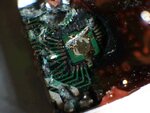
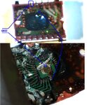
I found some cool looking 26-segment (28 if the "dot" LEDs work) LED displays (13 pins per digit) at a local surplus warehouse.
I've searched online for a datasheet, but I can't find anything.

There are only 14 pins coming out of each display, and it looks like there is an IC in it, because there is a glob of black (epoxy?) in the middle of the underside of the device, so I'm assuming it's gonna take something special to get a number displayed on it.

Any idea on some experiments I could do to figure out how this thing works?
If it helps, I have a PIC micro controller programer, a basic knowledge of C programming, and two PIC's (PIC12F675, and PIC16F886).

The info printed on the part is:
======================
LTM8494P
543
TAIWAN
======================

(attached are pics of the part)

Picture 70.jpgPicture 71.jpgPicture 72.jpgPicture 74.jpg
 

I noticed that each digit has 14 segments and it is clear that there are 2 digits... so perhaps the display is just a normal one; common anode or cathode. Did you try to light the LED segments as if there is no IC on it?
 

Even if we assume that the "dots" aren't connected (i.e. 13 segments per digit), that would still require a minimum of 27 pins total coming out of the device.
And yes - I did try powering a lot of the pins forward and backward, before I started this thread, then before I sent this reply, I checked ALL the pins forward and backward; no combination (of two pins) will light any segments.
 

You have there an IC circuit with LEDs on outputs… Need to find the datasheet in order to start working. :-D
 
In your case and if there is no IC, the display needs 16 pins only. The 14 segments of the two digits are connected together, say at their cathodes. Then the anodes of the 14 segments of the 1st digit are joined to form one common anode. The sample is for the 2nd digit. So in total there will be 14 cathodes for segments and 2 anodes for the digits. Available displays may have this described polarity or its opposite (anodes for the segments and cathodes for the digits).

Just to be sure, may I ask you how you tried to light the segments?
I mean did you test using the same method to light a single (discrete) red LED first?

You know, about what looks as an IC, I used not to believe what I see... for example, once I saw a nice looking small solar panel which is supposed to be the source supply of a calculator. It was just a well painted piece of plastic :) and the calculator was running on a hidden small battery.

Kerim
 
This type of display is part of early multi-digit seven segment display technology series. See some examples here:
**broken link removed**

Not so easy to test this circuit without the risk of damage...
 
Okay, it's definitely an IC. I chipped at it till I got the black glob off, but the IC came off with the glob, and it looks like I'd need a powerful microscope and some microscopic tools to get this stuff off the IC to read a part number. Attached pic is what was under the glob and IC.

Since these are useless as of now, I don't mind damaging them (but not my equipment). How much work are we talking, to test and possibly damage them? (I have three more of these devices, and there are more where they came from).
 

Attachments

  • Picture 75.jpg
    Picture 75.jpg
    76.1 KB · Views: 163
  • Like
Reactions: KerimF

    KerimF

    Points: 2
    Helpful Answer Positive Rating
It's usually called a dual 14-segment display with or without decimal points. It was made by LITEON in Taiwan but this is as close as I can get to the model:
**broken link removed**.

It appears to be some kind of smart or intelligent display instead of a simple multiplexed one. The chip inside would probably have the purpose of demultiplexing and latching the inputs so the display could run without flicker or multiplex dimming effect. If so, maybe you could identify the power and ground connections via ohmmeter and go from there.
 
I consider he already show us the GND pin. :smile:
Next step just to fix this GND pin and to play with a +5V power supply and do some tests. He will need to group some pins (arbitrary) and connect them to Vcc, rest of the pins to GND, later to change the groups, change the pins in the groups, and so on… a long, long way to go.
Try to consider there’s a need for the Vcc pin, also for enable the circuit (usually connected to GND), some pins for data/address/clock?, so lots of combinations to do, multiple times to change logical level for some pins(to simulate data transitions), keeping the others pins for a fix voltage. Good luck!
 

Attachments

  • GND pinout.JPG
    GND pinout.JPG
    67 KB · Views: 156
Alright, this looks like too much effort for something so cheap.
Still - thanks for all the input.

@mister_rf: thanks especially for pointing out the ground - great tip for a beginner like me.
 

If you are lucky, you may give a try for 10 minutes… who knows. :-D
 
Is anyone still interested in this thread? I too got a hold of a bunch of LTM8494P's. They were only 50 cents each and they had a huge box of them. But I believe they might be military spec parts because the place I go to for electronics does a lot of liquidating for defunct defense suppliers. It was mentioned by KJ6EAD in a previous post that it might be the LTP series from Liteon but I'm pretty sure the pinout and color specifications match the following LTM product in the link. Or it might be the LTM-8647AC. The only differences seem to be the AC is AIGaAs on non-transparent GaAs and the AP is GaP on transparent GaP substrate. They are also different in luminous intensity and wavelength. I'm not sure how to tell visually what substrate it is, but I assume since the 849 has a 'P' after it that the equiv is the AP:
**broken link removed**

I've been using the datasheet and looking at the traces on the back of the display seem to match up. Pin 13 visually looks connected to 14 and continuity is solid. I haven't had much luck in getting it to do anything though. I'm running 6V to the VDD and 3V to the VLED. I'm driving the clock with a 555 at 2Hz just for manual experimentation and have a toggle switch for the Data Enable and an push button switch for the Data Input. I was hoping that holding down the push button while setting data enable to low and then randomly holding down and releasing the Data Input switch would give me my 1 in the start bit and various other 0's and 1's throughout the 35 bits until the shift register loaded into the latches, but maybe the timing of the Data Enable and Data Input states are crucial. What do you folks think?
 
Success! It is indeed the pinout on the datasheet at **broken link removed** I think I will go back to the liquidation place and clean them out since the going rate online seems to be around $7 USD each.

The 555 timer drives it just fine and I was able to manually flip the switch and press the button during pulses turning on and off all segments. Of course it is all garbage (unless you are building a predator armband).

I want to do this old school and have some old 7489 64 bit Read/Write memory ICs that have been hanging out in my components cabinet that I can use to store all the data in and then use some parallel to serial shift registers and some other logic to sync the data enable and writing. Might make a 6 bit toggle loading interface with stepping and use the remaining 29 bits for simple commands to place in memory for things like scrolling when I multiplex a bunch of the displays together. Kind of a poor man's cosmac elf.
 
Nice work. That's a good find for a µC project with no multiplex dimming.
 

Thanks. I would have never thought to look at Liteon though. You led me there. I poked around the web forever before coming to this topic. Then I went through all their datasheets in the LTM series until I found one that kinda matched. I don't know if this one has data outputs like the 8647AP though. The pins are there but I can't seem to get anything out of them. I've tried to contact liteon several times but no emails back.

I did enhance my little testing environment though. It was too difficult to remember what pulse I was on so I added some decade counters and decoders and capped it at 36 with some nands and inverters. I still need to debounce my switches and buttons but I was able to manually light whatever I wanted. I decided to ditch the 7489 idea and maybe tear one of my old C64 floppy drives apart and use the 6502, the 2016 RAM, and the 6522 IO chip. Another thing I thought of is to use my old Casio FX-790P computer calculator. I found info on the 12 pin serial port and I can build an interface for that and add some timing and gate logic with some shift registers to stream it to the display. It only writes at 300 bits/sec but that is plenty if you are displaying it as scrolling text. I only have 10 of the displays so I'm maxed at 20 characters.

LiteonLedDisplayBoard.jpg
 
Status
Not open for further replies.

Part and Inventory Search

Welcome to EDABoard.com

Sponsor

Back
Top