Continue to Site

Welcome to EDAboard.com

Welcome to our site! EDAboard.com is an international Electronics Discussion Forum focused on EDA software, circuits, schematics, books, theory, papers, asic, pld, 8051, DSP, Network, RF, Analog Design, PCB, Service Manuals... and a whole lot more! To participate you need to register. Registration is free. Click here to register now.

Sawtooth generator circuit

Status
Not open for further replies.

Derekk02

Junior Member level 2
Joined
May 8, 2012
Messages
20
Helped
1
Reputation
2
Reaction score
0
Trophy points
1,281
Activity points
1,421
Hi all,

I'm looking for a circuit to build an sawtooth generator wich operates at about 10kHz.
Who can help me with that?

Derek


You could use a 555 timer in astable mode. Replace the charging R with a constant current source. The voltage across the C will then be a linear sawtooth.
 

I tried making a sawtooth with a 555. It works below 2khz. When I go higher the output signal dissapears.


Thank you.
I think this one is a good starting point.

http://www.edn.com/article/521198-Simple_sawtooth_generator_operates_at_high_frequency.php

What are suitable values for R and C to get 10khz?
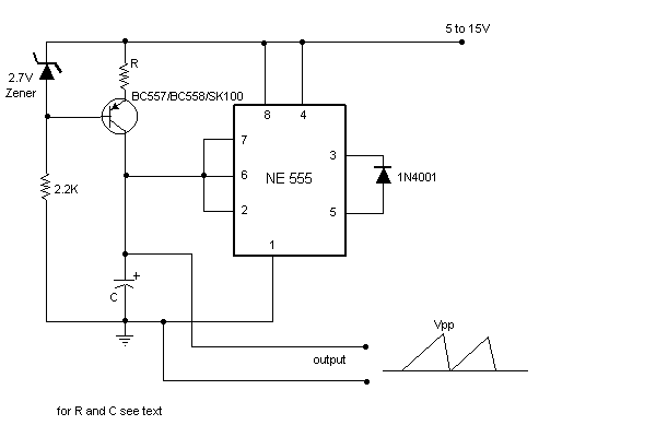
 

I tried making a sawtooth with a 555. It works below 2khz. When I go higher the output signal dissapears.

The 555 works to a much higher frequency than that - consult the data sheet. It may be worth your time playing with a 555, it's a very useful i.c.

I think this one is a good starting point.

**broken link removed**

You noticed this, didn't you? "Charging the RTCT network at constant voltage causes the ramp, so its response is exponential, approximately linear only for the initial part of the exponential rise.

What are suitable values for R and C to get 10khz?

The data sheet gives this information, as do many other web sites, one of which is
 

The other method is to use a binary counter and DAC. This will give an extremely linear sawtooth with a fast reset and can span full supply voltage but it does involve a slightly more complicated circuit.

Brian.
 

Here is a circuit diagram, which can help you to design a sawtooth generator:
544-18813c9c29.gif


:roll::cool:
 

Tomorrow I'm going to build the circuit that Goldsmith posted. I have a last question.
The pspice simulations show that the signal is from 0V to 10V. How can I arrange that the signal is from -10V to +10V?
 

I tried making a sawtooth with a 555. It works below 2khz. When I go higher the output signal dissapears.
If you use a smaller capacitor, it will go faster. Try a capacitor 10 times smaller than what you used before.
 

What values do you recommend?
 

I don't know what circuit you used before, but this should work. It's similar to what Jenifer posted before. The timing capacitor (C1) just needs to be small enough. 10nF should be OK. You can change R1 to set the frequency.


Dear Derekk02
Hi
If you want to have simultaneous sawtooth wave , it is pretty simple . add a simple potentiometer , and a negative voltage to one of it's heads and the other head to the sawtooth wave and then the out put will be from center head . so if you play with that potentiometer you can achieve simultaneous wave as well .
Best Wishes
Goldsmith
 

Status
Not open for further replies.

Similar threads

Part and Inventory Search

Welcome to EDABoard.com

Sponsor

Back
Top