Continue to Site

Welcome to EDAboard.com

Welcome to our site! EDAboard.com is an international Electronics Discussion Forum focused on EDA software, circuits, schematics, books, theory, papers, asic, pld, 8051, DSP, Network, RF, Analog Design, PCB, Service Manuals... and a whole lot more! To participate you need to register. Registration is free. Click here to register now.

24V/15A simple power supply

Status
Not open for further replies.

eric_s88

Newbie level 4
Joined
Nov 19, 2013
Messages
7
Helped
1
Reputation
2
Reaction score
1
Trophy points
3
Activity points
56
Hi everybody!
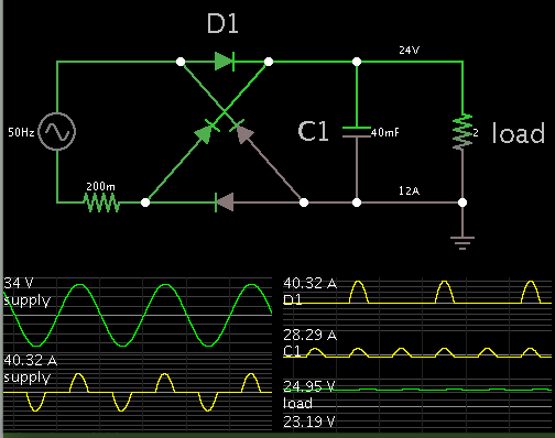
In a project I have a load that need about 12A (max) of current. and the voltage is 24V.
would this simple circuit response ??
I don't want high quality signal in output. so I want to use this simple circuit. cause it would be cheap!
one thing I worry about is inrush current of charging capacitor.

ps.jpg
 

A few things which you need to look at:
The VA Rating of your Transformer
Current Rating of your Rectifier
Ripple Current for your Capicitor (C1)

Otherwise your general circuit will work.

All of these are covered in this useful paper:
**broken link removed**

hope this helps
Mik
 
A few things which you need to look at:
The VA Rating of your Transformer
Current Rating of your Rectifier
Ripple Current for your Capicitor (C1)

Otherwise your general circuit will work.

All of these are covered in this useful paper:
**broken link removed**

hope this helps
Mik

Hey MiK , thanks for your reply. do you know some part number of rectifire power diodes for 12A current ?
can you suggest me a suitable VA rating ?

- - - Updated - - -

What about InRush current ?? it would be grate if I increase the cap value! ..
 

Bridge Rectifier: same or similar to this: https://uk.rs-online.com/web/p/bridge-rectifiers/2278744/
will be a good choice. Bolt it directly to the metal chassis you use to build your PSU onto.
Calculate your Transformer VA Rating from the previously attached link..... add a bit more (next size up for 'stock' transformers) to get better regulation of your output as the TX impedance will then be lower and temperature will also reduce.

Inrush current can be managed by using suitable NTC Thermistor in series with your Transformer Primary winding

Mik
 

One more thing:
if you use the same rating transformer Output voltage across capacitor wont be 24 , instead it will be ~34V(24 * root(2)). Capacitor will get charged to peak of the sine wave.
 

The capacitor needs to be at least 10 times bigger if you want anything like DC, and not just pulses.
 

As a 'rule of thumb' main reservoir capacitors should be at least 1000µF per Ampere of output current.

Thread title is for a 15A supply, so a suitable value could be 22,000µF at 40 Volts working whilst ensuring that the component has a suitable ripple current rating, in this case for 100Hz.

Mik
 
Last edited:

Simulation showing what goes on in a full-wave bridge supply, for these specs (starting at the transformer secondary):


The capacitor must endure current bursts upwards of 30A. It's a good idea to use a gang of capacitors, rather than one.

The Farad value shown results in ripple of one or two percent.

The 0.2 ohm resistor represents some amount of internal resistance in the secondary winding.

- - - Updated - - -

Inrush current at powerup can be several tens of A. My simulation shows over 100A, although the real amount will depend on internal impedance in your transformer.
 

Status
Not open for further replies.

Similar threads

Part and Inventory Search

Welcome to EDABoard.com

Sponsor

Back
Top