Continue to Site

Welcome to EDAboard.com

Welcome to our site! EDAboard.com is an international Electronics Discussion Forum focused on EDA software, circuits, schematics, books, theory, papers, asic, pld, 8051, DSP, Network, RF, Analog Design, PCB, Service Manuals... and a whole lot more! To participate you need to register. Registration is free. Click here to register now.

Relay based controlling of 54 watt DC motor and two 16 watt gear motors

Status
Not open for further replies.

umairk90

Newbie level 4
Joined
Oct 4, 2010
Messages
7
Helped
0
Reputation
0
Reaction score
0
Trophy points
1,281
Activity points
1,325
circuit diagram.JPG
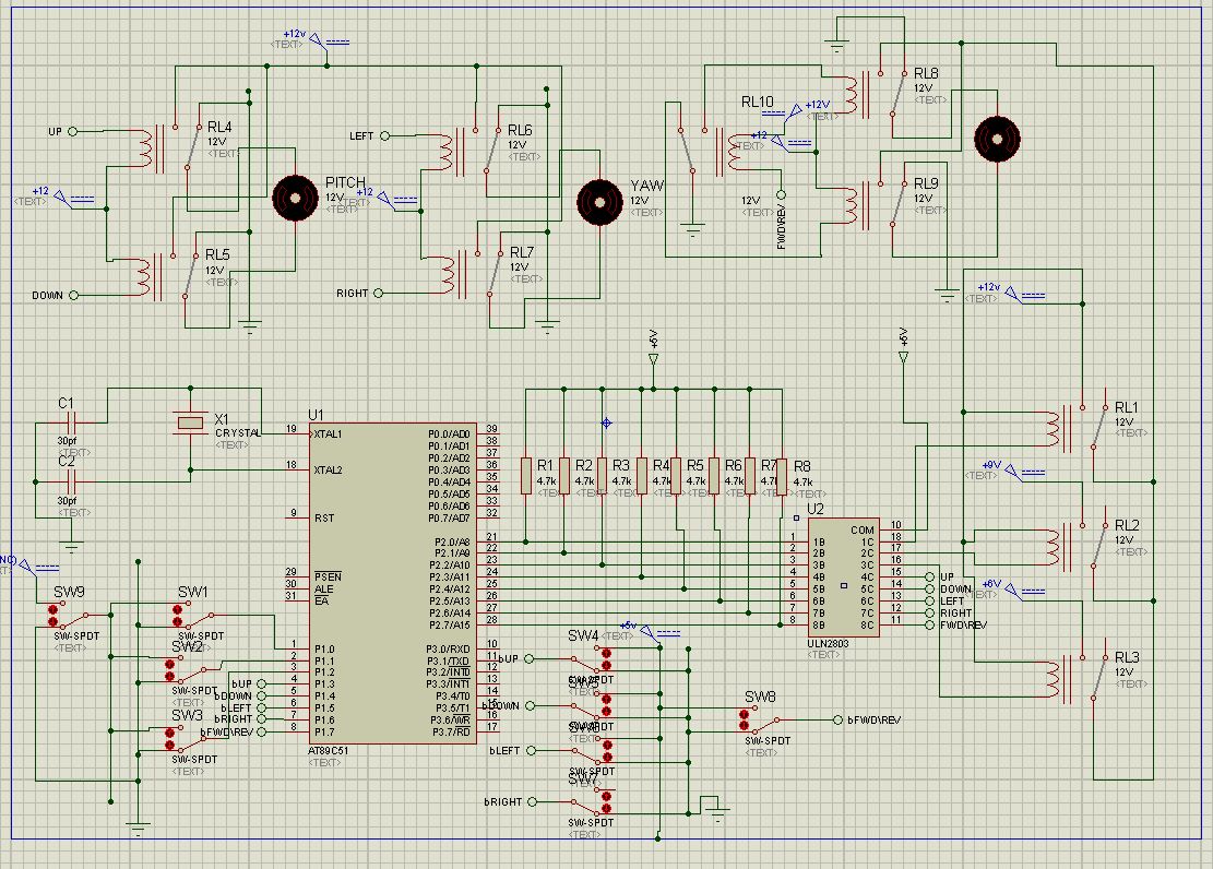
hi, i am having problem with these relays in this cricuit....some times they activate sometimes they dont... the 89c51 part is working fine as i have checked it by placing leds at the output of uln 2803... but i guess there is some problem in relay based circuitary.... can any one help me out plz...!


U3 COM pin should connect to the same supply as the relays (+12V) not +5V.

What is happening is the diodes internal to the ULN2803 are allowing some current to flow through the relays even when they are not supposed to be energized. The relay voltage is changing from 12V when energised to 7V when not energized. That's borderline on being low enough for the relay to operate.

Brian.


thnx for the reply... buddy I have given it +12V. Basically the problem is that sometimes the circuit works sometimes not... lets say i have made pin p1.0 high, the corresponding pin also gets high and the motor is turned on... but when i do it again after a while , it fails to activate the motor... note that i have checked the relay based circuitary without load... it worked fine.. also i have put a set of LEDs at the output of ULN 2803 which works fine when relay ckts are not connected (which proves that there is no problem in the program)... and this ckt diagram is working in the proteus simulation... i am so confused whats the main problem in the circuit and am unable to resolve it for the last 1 month!! Plz help..!!
 

I'm assuming ULN2803 pin 9 is grounded, the motors are bi-directional and will work at voltages of 6V to 12V.

The most likely cause is the microprocessor is crashing or doing something strange because of noise on the supply lines or pick-up on other pins as the relays operate. It's a common problem and difficult to track down. Things to check:

1. Is the RST pin really floating? Try pulling it up/down (whichever lets it run) with a resistor.
2. Are the capacitors and crystal connected with short wires and the ground side of the capacitors connected directly to the micro's ground pin?
3. Are the connections to the SW1, SW2 and SW3 on long wires? Try adding pull-up resistors, at the moment they float if not grounded.
4. Do you have decoupling capacitors close to the micro's suply and ground pins? Use at least 10uF and 100nF in parallel and as near to the chip as possible.
5. Are you relying on R1-R8 to bias the ULN inputs or is the micro driving the lines high? You might need lower than 4.7K to saturate the output transistors.


Brian.
 

thnx for the reply... buddy I have given it +12V. Basically the problem is that sometimes the circuit works sometimes not... lets say i have made pin p1.0 high, the corresponding pin also gets high and the motor is turned on... but when i do it again after a while , it fails to activate the motor... note that i have checked the relay based circuitary without load... it worked fine.. also i have put a set of LEDs at the output of ULN 2803 which works fine when relay ckts are not connected (which proves that there is no problem in the program)... and this ckt diagram is working in the proteus simulation... i am so confused whats the main problem in the circuit and am unable to resolve it for the last 1 month!! Plz help..!!

No code is attached. I dont know the sequence of activation of the relays and types of the relays. Please note that the current that each output of ULN2803 can give depends on the number of outputs used and the duty cycle.

Also follow the following diagram to connect a relay:-
ULN2803-relay.JPG
 

What type of relays you are using?
 
Last edited:

Status
Not open for further replies.

Part and Inventory Search

Welcome to EDABoard.com

Sponsor

Back
Top