Continue to Site

Welcome to EDAboard.com

Welcome to our site! EDAboard.com is an international Electronics Discussion Forum focused on EDA software, circuits, schematics, books, theory, papers, asic, pld, 8051, DSP, Network, RF, Analog Design, PCB, Service Manuals... and a whole lot more! To participate you need to register. Registration is free. Click here to register now.

230v - 5V transformerless PSU, which schematic is better?

Status
Not open for further replies.

neazoi

Advanced Member level 6
Joined
Jan 5, 2008
Messages
4,119
Helped
13
Reputation
26
Reaction score
15
Trophy points
1,318
Location
Greece
Activity points
36,918
Hello I am building a microcontroller project using an ATMega644. Acording to the datasheet this draws less than 1mA at 1MHz, although I run it at 20MHZ in my project.

I need to make a transformerless PSU for this project and I have found two schematics.
https://www.learningelectronics.net/circuits/transformerless-5-volt-power-supply.html
https://www.learningelectronics.net/circuits/low-power-12v-transformerless-power.html

One of these is much more simple, so I turn towards this one. I also like this simpler one because "the zero voltage reference of the DC voltage is not directly connected to the neutral line of the 230-V circuit". I do not know what it means but it seems more safe.

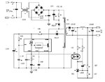
I would like to know If I can additionally connect a 250VAC varistor and a fuse at the input, like shown in the attached schematic?
 

Attachments

  • psu.gif
    psu.gif
    16.2 KB · Views: 104
Last edited:

For your micro project these circuits is not suitable. It has a no isolation

- - - Updated - - -

IT WILL BE BETTER TO USE 230VAC/ 9VAC TRANSFORMER & 7805 IC
 
  • Like
Reactions: neazoi

    neazoi

    Points: 2
    Helpful Answer Positive Rating
For your micro project these circuits is not suitable. It has a no isolation

- - - Updated - - -

IT WILL BE BETTER TO USE 230VAC/ 9VAC TRANSFORMER & 7805 IC

As I said, I try to avoid transformer, since space is very very limited, where the wircuit needs to be installed.
I am thinking of using a 78L05 regulator (1mA consumption) at the output of the attached schematic, so that the output voltage is more stable.
Why this is not suitable for the micro?


* Another idea I had was to use the attached schematic to drive a virtual ground system https://tangentsoft.net/elec/vgrounds.html or this one https://tangentsoft.net/elec/bitmaps/vgrounds/vfb-opa.png
Will this isolate the newtral, for a more safe PSU?
 
Last edited:

There is option to use small SMPS. Buy adapter for phone or some similar device, extract PCB and use it in your project. You will pay 2-3eur for this. Of course you can make your own small SMPS adapter if you wish.

Another option is to use small AC/DC converters, but price is not popular.


Even cheapest chinese products today dont have transformeless psu.


Additional consideration for tranformeless and other mains power power supplies is to use Live on Neutral place and vice versa. At wall socket for mains power you dont have marked what is Live and what is Neutral, all depends how user connect plug in wall socket. Because that some transformerless designs are very very dangerous.

Always look to use isolation in designs.


Best regards,
Peter
 
  • Like
Reactions: neazoi

    neazoi

    Points: 2
    Helpful Answer Positive Rating
Additional consideration for tranformeless and other mains power power supplies is to use Live on Neutral place and vice versa. At wall socket for mains power you dont have marked what is Live and what is Neutral, all depends how user connect plug in wall socket. Because that some transformerless designs are very very dangerous.

Always look to use isolation in designs.

Best regards,
Peter
Yes you are right about this. It reminds me of the old transformerless tube transmitters. I think this is a problem with all these transformerless designs. But in a bridge configuration this would not matter I think. The ony circuit that is affected is the one BEFORE the bridge.

In the attached schematic, If I include another F1, R1 and C1 on the other pole?

Also Is there any way I can build a 1:1 isolation transformer using small amidon toroids with low turns at home? This would be a feasible solution, but all the transformers I have seen use large number of turns.
 

Last edited:

use st micro electronics viper12a series based smps

- - - Updated - - -

this is the simplest & efiicient circuit for smps. 5volt 3a . dont look any other desgins. isolated from mains no shock hazard.
 

Attachments

  • 12.jpg
    12.jpg
    42.4 KB · Views: 109

use st micro electronics viper12a series based smps

- - - Updated - - -

this is the simplest & efiicient circuit for smps. 5volt 3a . dont look any other desgins. isolated from mains no shock hazard.

It still includes a transformer! what is the good of it so?
 

the transformer is a miniature size. if you want isolation from mains then this is the best one.
 
  • Like
Reactions: neazoi

    neazoi

    Points: 2
    Helpful Answer Positive Rating
the transformer is a miniature size. if you want isolation from mains then this is the best one.

Look at T1. What if I connect it in parallel, so that it counts for an isolation transformer? These have low number of turns, found inside PSUs.
Can it be done?
 

the entire circuit can be made on 1.5square inch pcb

- - - Updated - - -

t1 is a cmc choke used for filteration it cannot be used as isolation transformer.
 
  • Like
Reactions: neazoi

    neazoi

    Points: 2
    Helpful Answer Positive Rating
the entire circuit can be made on 1.5square inch pcb

- - - Updated - - -

t1 is a cmc choke used for filteration it cannot be used as isolation transformer.

This goes back to transformer theory, but I wonder why an isolation transformer should have large amount of turns? Why say a 10T:10T transformer is not enough (considering low currents)?
 

if your mains voltage is 230vac 50hz then we have to choose a low frequency iron core transformer, the size will increse in low frequency. in smps 100khz frequency is used so the size of the transformer will decrese

- - - Updated - - -

in mains iron core transformer primary should be high turns to get the required wattage
 
  • Like
Reactions: neazoi

    neazoi

    Points: 2
    Helpful Answer Positive Rating
this transformer is 19mm x22mm : smaller than your X1 capacitor !
**broken link removed**
 

Transformerless power supplies are used for electronic devices that don't require safe isolation from mains, e.g. PIR light switches, small plug-in energy meters, some home appliances. They are only applicable if no external signals need to connect to the electronic and the enclosure prohibits exposure of circuit parts. In simple words, any circuit directly connected to the mains needs the same isolation as the mains itself, even if it's using low voltage.

Many threads at edaboard asking for transformerless power supplies are apparently unware of these limitations. So the same warnings have to be repeated again and again.

In the present case (< 100 mW power consumption), my personal favourite would be a small 50 Hz transformer, as suggested. You can buy rather small off-mains switched mode supply modules, but hardly design them at home. Number of transformer turns will be ruled by flux (∫Vdt) limits of the core rather than current, even a high frequency transformer in a switched mode supply will need a considerable number of turns (e.g. 500 or 1000) for the primary winding when it's small. (You don't need to ask if you bring some basic physical laws to mind.)
 
Last edited:
  • Like
Reactions: tpetar

    tpetar

    Points: 2
    Helpful Answer Positive Rating
  • Like
Reactions: FvM

    FvM

    Points: 2
    Helpful Answer Positive Rating
Both are over complicated an none offers mains isolation, so safety is about the same. This should not be much of a problem for the low currents involved.

Read the description carefully:

To archive this what you need is is a capacitor (with an optional resistor, although for the sake of efficiency I would omit the resistor and use a fuse instead, followed by a bridge rectifier (600V rated). The output is clamped by a 5Watt or so zenner depending on your power requirements.

To calculate the value of the capacitor you would need to calculate the current you need for your circuit. Say you have 220VRMS and need a maximum of 20mA, them by ohms law you should use a resistor with a value of 10KOhm. Such resistor would have a loss of P = U*I => 220*0.020 = 5Watt.

Using a capacitor, means, instead of wasting these 5 Watts in the resistor power is returned to the grid as reactive energy, so effectively your circuit will not overheat and you will not be billed for those aditional 5Watt the resistor would otherwise dissipate as heat: Only the power your circuit draws, plus a bit for any losses on the capacitor (0.01Watt maybe).
For a mains frequency of 50Hz and a Xc (equivalent resistance) of 10KOhm you need a 300nF Capacitor.

For safety you might want to use one 600nF capacitor on both Phase an Neutral, instead of just a 300uF capacitor in series with the phase. This narrows it down to 6 parts.

The circuit would look like: (Phase) 50mA fuse -- Capacitor -- Bridge Rectifier (From the output of the capacitor to Neutral) and then after the bridge rectifier a zenner and, DC-Link Filter capacitor.

Here is the calculator, just in case you want to play with the values http://www.sengpielaudio.com/calculator-RC.htm
 
Last edited:

Status
Not open for further replies.

Similar threads

Part and Inventory Search

Welcome to EDABoard.com

Sponsor

Back
Top