Continue to Site

Welcome to EDAboard.com

Welcome to our site! EDAboard.com is an international Electronics Discussion Forum focused on EDA software, circuits, schematics, books, theory, papers, asic, pld, 8051, DSP, Network, RF, Analog Design, PCB, Service Manuals... and a whole lot more! To participate you need to register. Registration is free. Click here to register now.

230 volts ac to 450 DC and 5 amps power supply....

Status
Not open for further replies.

aliraza786

Full Member level 4
Joined
Nov 10, 2009
Messages
210
Helped
14
Reputation
28
Reaction score
14
Trophy points
1,298
Location
Lahore, Pakistan, Pakistan
Activity points
2,914
sir i want to convert my home mains supply which is 230 volts ac to 450 volts Dc and 5 amp capacity.... which type of inverter i should use... kindly help me thanks :)... and it must has protection if load try to draw more current it gives only maximum 5 amp current and dnt shut the power off....
 

Use 35A bridge rectifier 6x3300uF,600V capacitor and voltage doubler of appropriate value components. your first stage (Rectifier and filter) must be greater than 10A the voltage doubler will double the voltages to 460V approx: with the reduction of current to approximately half. try it.

Regards
 

This is just to give an idea or two. What you're asking will require use of caution in design and construction.

(A) You might use a voltage doubler. Greinacher (bridge type) can handle the high A better than the Villard type.

Output volt level will soar with a light load. If you want 5 amps at 450 V then your overall load is 90 ohms. This may or may not bring volt level down to what you want.

Components will carry bursts of current, maybe 20 or 40 amps. You'll want to use multiple capacitors. Maybe multiple diodes as well.

(B) Or a boost converter. This method is more complicated.

Again one way or another, components will need to carry current bursts up to 20 or 40A during part of the cycle, if you want to get 5A at 2X nominal mains VAC.

Regulation is easier with the switched coil converter, than with the voltage doubler.
 

thanks to both for you suggestions... then what is the good and easy method for this.... what is switched coil converter...?

- - - Updated - - -

and if i need just 5 amp and 230 mains voltage in that case which type of circuit i need........?
 

Easy method is Linear converter i.e; using rectifiers and filters; switch mode method is complex and a newbie is not advised to go through.

if u need just 5A at 230V DC so just use any bridge greater than 15A and 2x3300uF capacitors. it is the simplest way to go. but this circuit is Extremely dangerous and one may have life Risk if not handle with care. high AC currents can give a jerk of electric shock but DC current don't leave the person till death.
 

As I think about it a little more...

In view of the amount of power we are talking about, you might consider a 2X step-up transformer.

Average power through your system is 2.3 kW. However it is conveyed in momentary surges. Components will need to carry bursts of several kW during the peaks of the sinewaves. The momentary high amp surges place a high demand on all parts of the system.

On the other hand a transformer will have an easier time handling all this, and it will add a measure of safety as well. It will draw the same average amps from the mains, but the surge will be spread out over more of the cycle. This will reduce the stress on all parts of the system.

The transformer should be rated at least 2.5 kW.

It can be an autoformer to reduce expenses. This has one coil in common with both the primary and secondary.

what is switched coil converter...?

This is a method which has a single inductor at the center of action. It uses inductive kick to step a supply level up or down.

and if i need just 5 amp and 230 mains voltage in that case which type of circuit i need........?

A full-wave diode bridge and smoothing capacitor is commonly used.

See the bottom half of the webpage given below.

https://www.electronics-tutorials.ws/diode/diode_6.html
 

sir i want to convert my home mains supply which is 230 volts ac to 450 volts Dc and 5 amp capacity.... which type of inverter i should use... kindly help me thanks :)... and it must has protection if load try to draw more current it gives only maximum 5 amp current and dnt shut the power off....

Use step up transformer 230V to 450V, and on secundar 450V use full bridge for rectification.

If you cant find that trafo in shops, you can order trafo from some manufacturer or rewind yourself,

or

you see some similarity with 110V to 220V ?
 

tpetar sir .... thaku so much for you suggestions... i tried dimmer today.... but it change volatge from 230 to 160 volts AC.... Transformer is costly solution and hard to find.... and winding my own transformer is very time consuming .... if i use 15A bridge rectifre and then filter of 2 3300uf 400 volts caps and after that current limiter ... isn't it a cheap solution..? but the only thing is that how can i control current at 230 volts DC ..??
 

We now have several threads probably for the same thing.

Tell me this 220V to 450V is for that electromagnet ?
 

if i use 15A bridge rectifre and then filter of 2 3300uf 400 volts caps and after that current limiter ... isn't it a cheap solution..? but the only thing is that how can i control current at 230 volts DC ..??

Your component values appear to work in simulation.

This reply is assuming your load will draw 2.5 A at 230 V (half of what you intended to draw at 460V).

Notice that two capacitors will share 2.5 A, so each will have at least 1.25 A going through it continually. If they overheat, you should make a 3-cap bank, or 4-cap bank, etc.

Volt output will find an equilibrium level between 230 and 340 VDC, depending on what is the current demand by your load, drawn from the capacitors.

To regulate it will require a transistor/mosfet rated to endure that volt range, and that current.

To reduce volt output, you can try installing a capacitor somewhere in series with AC. It should be non-polarized. Probably a few hundred uF. It will carry several amps, so considering using a few in parallel.

As post #5 stated, you are working with high voltage and high power, with hazards that can result in disaster.
 

sir if i installed capacitor in seriers then it will reduce the AC voltage mostly likely as it done in transformer less power supplies right.? and sir what is protection googles.?
 

sir if i installed capacitor in seriers then it will reduce the AC voltage mostly likely as it done in transformer less power supplies right.? and sir what is protection googles.?

yes non-electrolytic capacitors in series with AC line reduce AC voltages to a large extant; i.e; from 220V to 25V approx: This method is mostly used in transformerless linear power supplies, installed in LED emergency lights. protection Googles means protection Glasses (Aiynak). because these capacitors can blast in high voltages; since these are ceramic(China mitti) capacitors so you can imagine what can happen when these capacitor blast. so eye protection is necessary.
 
Last edited:
Transformeless power supply using internal resistance of some unipolar capacitor and resistance of resistor to decrease voltage from 220V to let say 50V-30V is used for lower current 5mA-100mA, in other words for few watts. Higher current can be achieved but capacitor should be bigger, and his price will be also bigger, also he need more space. In that case use trafo.

Eyes protection googles :

products%5CSAFETY%20PRODUCTS.A2.EYE%20PROTECTION.EYEPRO%5CHIGH-IMPACT%20UV%20PROTECTIVE%20GOGGLES.EYEPRO%20%20%20R%5CEYEPRO%20%20%20R_primary_WebPic1.JPG


If you want to try to drain few amps over this capacitors use like this protective googles, capacitor may explode.
 
qaiser capacitor in DC line will block the DC isn't..?? capacitor in AC line reduce ac.... and if u use more capacitor ... like 6,, 3300uf,, 400 volts capsitor then current will divide more and reduce the chances of blast right.? now the problem is about current limiting circuit.? i know about low power current limiter circuit but how to make high power current limiter circuit .. becuse i have enormous current at input in case of short everything will burnt of fire up.....
 

qaiser capacitor in DC line will block the DC isn't..?? capacitor in AC line reduce ac.... and if u use more capacitor ... like 6,, 3300uf,, 400 volts capsitor then current will divide more and reduce the chances of blast right.? now the problem is about current limiting circuit.? i know about low power current limiter circuit but how to make high power current limiter circuit .. becuse i have enormous current at input in case of short everything will burnt of fire up.....

Bipolar (for DC) and unipolar (AC) capacitors are different.

At AC unipolar capacitor is abused to lower AC voltage with his internal resistance, but in this process capacitor does not develop heat like resistor. In this way power supply current should be in mA range 5mA-100mA or few watts.
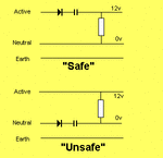
However, the capacitor that will be required will keep growing in size as the current increases, and at some point it becomes more sensible to use a transformer instead. This transition point occurs at around 100 mA in practice. An X2 class capacitor with a rating of 1.5 μF/250 V~ is nearly the same size as a mains transformer rated 2×9 V/100 mA. At still larger currents, the space required for a high voltage, bipolar, foil capacitor would exceed that of a suitable transformer. Taking electrical safety into consideration as well, it obviously becomes preferable to use a transformer instead.

Transformeless Supply Safe & Unsafe.gif


Transformerless Power Supplies: Resistive and Capacitive
 

Attachments

  • 00954A.pdf
    248.6 KB · Views: 101
Last edited:

qaiser capacitor in DC line will block the DC isn't..?? capacitor in AC line reduce ac.... and if u use more capacitor ... like 6,, 3300uf,, 400 volts capsitor then current will divide more and reduce the chances of blast right.? now the problem is about current limiting circuit.? i know about low power current limiter circuit but how to make high power current limiter circuit .. becuse i have enormous current at input in case of short everything will burnt of fire up.....

Sorry i mistaken wrote DC instead of AC.
Yes as Tpetar said. the Series unipolar or non-electrolytic capacitor is used in series to drop the voltages down but this method is used for mA current requirements. for large currents you have to use Transformers. if you want to avoid bulky transformers used for large current supplies like UPSes and Stablizers (you may commonly have seen them) you have to adopt switch mode technology which is more complex than linear one.. in switch mode power supplies (SMPS) (e.g; power supplies of PCs and Laptop adoptors, and small Chinese Silver color inverters) Transformers are still present but there sizes shrinks because of high switching frequency used in these supplies.

secondly don't use electrolytic capacitors 3300uf,, 400 volts in series with any power supply it may burst your capacitor due to polarity reversal. instead you can use 104J, 450V capacitors in series with AC rail as Tpetar uploaded the image.

i recommend you to use Transformers if you need high currents. up to 10A transformers(12v+12V step down) of Voltex company are easily available with reasonable sizes and wights in Pakistani markets. for special 2Xstep up transformers you can get them by ordering any technician shop who make transformers for stabilizers.
 

Status
Not open for further replies.

Similar threads

Part and Inventory Search

Welcome to EDABoard.com

Sponsor

Back
Top