Continue to Site

Welcome to EDAboard.com

Welcome to our site! EDAboard.com is an international Electronics Discussion Forum focused on EDA software, circuits, schematics, books, theory, papers, asic, pld, 8051, DSP, Network, RF, Analog Design, PCB, Service Manuals... and a whole lot more! To participate you need to register. Registration is free. Click here to register now.

What is load cell ? How it works ? thanks

Status
Not open for further replies.

phatcreators

Full Member level 5
Joined
Sep 2, 2011
Messages
315
Helped
24
Reputation
48
Reaction score
24
Trophy points
1,298
Activity points
3,458
What is load cell ? How it works ?

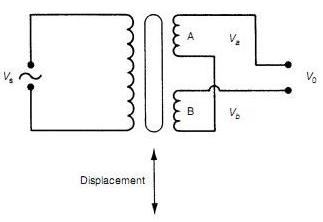
Inside it there are two small (tiny) transformers whose one wire is common to each other and there are two other wires (one for each).

How to test it or check it, whether its working fine or not ?

They are usually connected with a shaft (roller) that rotates and take the packaging film to the rewinding shaft.

thanks
 

Load cell - Wikipedia, the free encyclopedia

https://image.made-in-china.com/2f0j00CMJQhHdlZabR/Compression-Load-Cell-GY-2-.jpg


A load cell is a transducer that is used to convert a force into electrical signal. This conversion is indirect and happens in two stages. Through a mechanical arrangement, the force being sensed deforms a strain gauge. The strain gauge measures the deformation (strain) as an electrical signal, because the strain changes the effective electrical resistance of the wire. A load cell usually consists of four strain gauges in a Wheatstone bridge configuration. Load cells of one strain gauge (quarter bridge) or two strain gauges (half bridge) are also available. The electrical signal output is typically in the order of a few millivolts and requires amplification by an instrumentation amplifier before it can be used. The output of the transducer is plugged into an algorithm to calculate the force applied to the transducer.

but there are no resistors or wheatstone bridge configuration
there are two small transformers .
there's no input wire or cable ..... there's just output cable having three wires coming out from the two transformers in which one wire is common to both the two transformers .....

there are total 2 wires out of one transformer

thanks
 

Here is heavy info package...............

Load cells
Load Cell - Load Cells | Load Cell Accessories | Load Cell Displays | Load Cell Instruments

Troubleshooting Guide
**broken link removed**

Applications | Load Cell
Load Cell Application | Load Cell Applications

You wrote about shaft , there is Rotary Torque Sensor Models too.......
Torque Sensor | Torque Sensors

Applications | Torque Sensor
Torque sensor application | Torque sensor applications

How load or force cell work
how sensors work - load cells

Introduction to Load Cells
Load Cell

LOAD CELL TECHNOLOGY IN PRACTICE
https://www.aeroconsystems.com/electronics/load_cell_primer.pdf
 
One more good web link with digital and quasi-digital load cells information:
Load Cells
 

Hi,
Your specified design is known as LVDT method of Load cells. As the name LVDT is, it is Linear Variable Differential Transformer.

They are usually connected with a shaft (roller) that rotates and take the packaging film to the rewinding shaft.
This seems to me a bit different thing as compared to the Weighing relation.
Anyways the measuring method is that the transformer has one primary supplied with AC and two secondaries wired in opposite phase, as it is called Differential transformer the output is Proportional to the displacement of the Core which is directly connected to the Weighing Tray.
If you need complete theory, please ask as it is bit lengthy. Here is a general diagram of the transformer.
59_1319640553.jpg
 
The description clearly refers to an inductive transducer. Instead of the suggested LVDT design, it sounds more like center-tapped coil, that works in combination with a moving core and a differential inductance bridge.
 
Hi phat,
Can you upload an image of this ?

they provide the required tension to the packaging film, so the film can be printed & re-winded properly .......
they are two on each shaft (roller) one on the right side and other on the left side .......

thanks a lot though

---------- Post added at 23:34 ---------- Previous post was at 23:32 ----------

Here is heavy info package...............

Load cells
Load Cell - Load Cells | Load Cell Accessories | Load Cell Displays | Load Cell Instruments

Troubleshooting Guide
**broken link removed**

Applications | Load Cell
Load Cell Application | Load Cell Applications

You wrote about shaft , there is Rotary Torque Sensor Models too.......
Torque Sensor | Torque Sensors

Applications | Torque Sensor
Torque sensor application | Torque sensor applications

How load or force cell work
how sensors work - load cells

Introduction to Load Cells
Load Cell

LOAD CELL TECHNOLOGY IN PRACTICE
https://www.aeroconsystems.com/electronics/load_cell_primer.pdf


ample thanks to you

can we test it ? If yes then how ?

thanks in advance
 

can we test it ? If yes then how ?

Yes we can,
but how...... it depends the type of device and connector wiring.

First we need to know manufacturer and exact type and model codes and numbers,
then we must try to find all data and wirings for device.
 
Yes we can,
but how...... it depends the type of device and connector wiring.

First we need to know manufacturer and exact type and model codes and numbers,
then we must try to find all data and wirings for device.

How to test LVDT ?

Can LVDT be used as a strain gauge ?

thanks
 

How to test LVDT ?

Look live principle first here........
How it Works - LVDT

As you findout for testing you need,
supply ac-signal to primary and
check secondary output with scope.

Supply voltage and frequency can vary between different LVDT types.
Usually (50....15000Hz )

For test supply you can use for example 5Vac 50Hz with 100 ohm 1/4W series resistor ,
connected for protect primary against overcurrent.

Allways 1. thing to do before testing , find out electrical data and connections.

Coils can simply check with ohm-meter. ( only for check , are coils fully damaged )

Some LVDT types have secondary midpoint output connection too. ( 3 secondary pins )

Test connection...............
LVDT TestCircuit_01.jpg

Can LVDT be used as a strain gauge ?

No.
But LVDT can be used indirect for force measurement with different mechanical solutions
by converting the tension or force into a linear or angular movement.

Linear Variable Differential Transformer (LVDT)
is a type of electrical transformer used for measuring linear (i.e. translational) displacement.
Metrolog - LVDT Transducers

Same principle are used in rotary variable differential transformer (RVDT)
It is a type of electrical transformer used for measuring angular displacement.
Metrolog - RVDT Transducers
 
HI phatcreator,
Can you give me the Brand name and the model number of the machine in which these are used?
 
HI phatcreator,
Can you give me the Brand name and the model number of the machine in which these are used?

HAN MI is the brand name of strain gauge which are present on both sides of the roller.
The machine is very old of its kind, having only maximum 6 color job printing facility
there are heaters , ink trays .... unwind shaft & rewind shaft both are present.
the strain gauges are connected with tension controller boxes that can control the tension manually and also automatically.

the tension controller box contains the " TIP 31c " , " TIP 142F " & " 4558D (Ic) " and other circuitry ......

thanks

---------- Post added at 14:32 ---------- Previous post was at 14:20 ----------

Look live principle first here........
How it Works - LVDT

As you findout for testing you need,
supply ac-signal to primary and
check secondary output with scope.

Supply voltage and frequency can vary between different LVDT types.
Usually (50....15000Hz )

For test supply you can use for example 5Vac 50Hz with 100 ohm 1/4W series resistor ,
connected for protect primary against overcurrent.

Allways 1. thing to do before testing , find out electrical data and connections.

Coils can simply check with ohm-meter. ( only for check , are coils fully damaged )

Some LVDT types have secondary midpoint output connection too. ( 3 secondary pins )

Test connection...............
View attachment 63440


No.
But LVDT can be used indirect for force measurement with different mechanical solutions
by converting the tension or force into a linear or angular movement.

Linear Variable Differential Transformer (LVDT)
is a type of electrical transformer used for measuring linear (i.e. translational) displacement.
Metrolog - LVDT Transducers

Same principle are used in rotary variable differential transformer (RVDT)
It is a type of electrical transformer used for measuring angular displacement.
Metrolog - RVDT Transducers

Thanks a lot,

as you mentioned in your text that, " Some LVDT types have secondary midpoint output connection too. ( 3 secondary pins ) " .... So, the testing circuit that you provided is enough to test this type of LVDT in the same as a normal LDVT ??

What should be the coils ohmic values for a given LVDT ? Can you take any example of it ?

Referring to the links that you provided, " Metrolog - LVDT Transducers "

there are different images of different types of LVDTs , but how to apply the testing circuit procedure to any of these ?

which one is the primary ? which one is the secondary ? which one should be taken as output ? which one taken as ground ?

thanks
 

as you mentioned in your text that, " Some LVDT types have secondary midpoint output connection too. ( 3 secondary pins ) " .... So, the testing circuit that you provided is enough to test this type of LVDT in the same as a normal LDVT ??

goto Metrolog - LVDT Transducers (AC output)
and select for ex. PCA-116 Series
you find LVDT Schaevitz® Transducers - PCA-116 Series
open PDF for datasheet
you find this page https://www.metrolog.net/files/tech...splacement/gagehead/pca_116_enus_metrolog.pdf

There you find all data needed for normal use.
-specifications
-dimensions
-wiring

What should be the coils ohmic values for a given LVDT ? Can you take any example of it ?
look allways first at datasheet.........
for ex. PCA-116-100
Primary 660 ohm , secondary 960 ohm

there are different images of different types of LVDTs , but how to apply the testing circuit procedure to any of these ?
which one is the primary ? which one is the secondary ? which one should be taken as output ? which one taken as ground ?

again look allways first at datasheet.........
-this type of LVDT dont care which wire is GND, only transformer phase shifts 180 degrees.
for ex. PCA-116-100 test circuit............
LVDT TestCircuit_02.jpg

But remember there is lots of different versions of basic principle of LVDT
look dataseets again..........
- AC output as above
- DC output
- current loop output
- RS-485 output
- USB output
- etc, etc.....
 
goto Metrolog - LVDT Transducers (AC output)
and select for ex. PCA-116 Series
you find LVDT Schaevitz® Transducers - PCA-116 Series
open PDF for datasheet
you find this page https://www.metrolog.net/files/tech...splacement/gagehead/pca_116_enus_metrolog.pdf

There you find all data needed for normal use.
-specifications
-dimensions
-wiring


look allways first at datasheet.........
for ex. PCA-116-100
Primary 660 ohm , secondary 960 ohm


again look allways first at datasheet.........
-this type of LVDT dont care which wire is GND, only transformer phase shifts 180 degrees.
for ex. PCA-116-100 test circuit............
View attachment 63477

But remember there is lots of different versions of basic principle of LVDT
look dataseets again..........
- AC output as above
- DC output
- current loop output
- RS-485 output
- USB output
- etc, etc.....

bundle of thanks to you

kindly, explain about " Schaevitz " , what is this, " Compatible with All Schaevitz® Signal Conditioners " ?

also, how to test this one : LCIT Series (DC Output) https://www.metrolog.net/files/tech...near_displacement/lvit/lcit_enus_metrolog.pdf

thanks
 
Last edited:

  • Like
Reactions: munzir

    munzir

    Points: 2
    Helpful Answer Positive Rating
Status
Not open for further replies.

Similar threads

Part and Inventory Search

Welcome to EDABoard.com

Sponsor

Back
Top