Sajjadkhan
Full Member level 5
- Joined
- Sep 25, 2010
- Messages
- 307
- Helped
- 17
- Reputation
- 34
- Reaction score
- 16
- Trophy points
- 1,298
- Location
- Rawalpindi,Pakistan
- Activity points
- 4,199
I want to measure voltage up to 51V (with 0.1V accuracy). Up to 25.5V can be easily measured as 0.1V/bit.
Using a voltage divider which gives 5v on 51V. here is what i want to do.
Vref (-) = 0v, vref(+)=2.5V ---> the adc can measure up to 25.5v.
When analog voltage reaches to 25.5V (i.e. adc value = 255 dec)my 8052 will switches Vref(-)=2.5 and Vref(+)=5.Now if adc output is 0 then it means the previous 25.5 was the answer but if the output of the adc is suppose 15 decimal then voltage is 25.5 + 1.5 =27V.
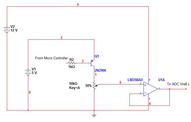
Problem is with Vref(-). I used a PNP transistor, emitter connected to 5v supply and collector is connect to POT upper leg, mid leg is fed to voltage follower and 3rd leg is grounded. The base of the PNP is connected to a resistor which is then connected to Mikro Controller. The POT is tuned so that when there is 0V on PNP base then there will be 2.5V at the POT mid leg and so as voltage follower op-amp. and when 5 v on the base then 0V on op-amp.
The circuit alone works fine but when connected to Vref(-) then there is always 0.66-0.7V on Vref(-). What causes the problem?
Here is the schematic, just made. The 12 V supply is unregulated but 5v is regulated using lm317 and capacitor filter was also used at theoutput. when controller pin is set to 1 i.e 5v the op-amp gives 0v and when controller pin is set to 0v then 2.5 V. Circuit is good when not connected to Vref(-). I don't think 0.7V exist in this area except emitter-base region.
The possibility i m thinking is since its a ladder network i.e. 256 resistors and op-amp has its own low out-put impedance so its like a small resistor is added at the bottom dude to which potential drop is occurring. what u think?
And if its so then there is no solution to my problem then. i can use a npn transistor i.e. its collector connected to Vref(-) but no transistor is perfectly saturated so this idea also fails. Can't use relay since i have to check value after every 1 sec and that would be noisy.
All values in the fig are exact.
---------- Post added at 06:16 ---------- Previous post was at 05:11 ----------
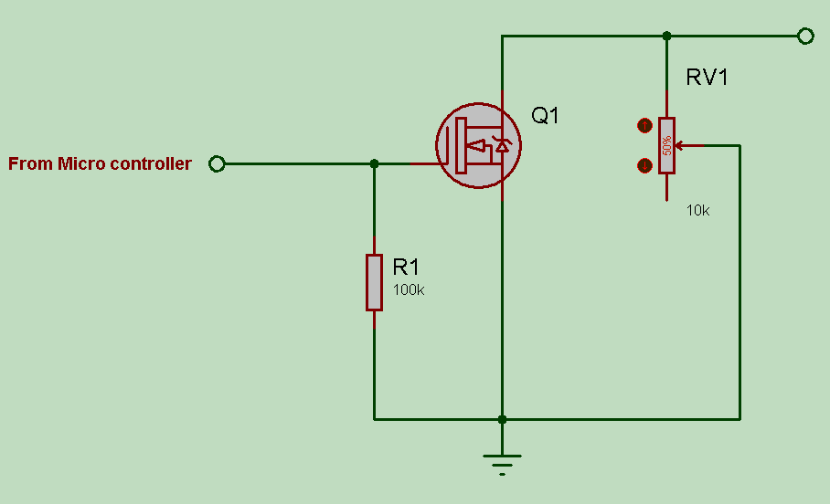
I just got an idea, a possibility. that to give 2.5V at Vref - i use the existing circuit and for grounding i use a mosfet which has lowest drain to source impedance. The error would be too less. Any thoughts?
Using a voltage divider which gives 5v on 51V. here is what i want to do.
Vref (-) = 0v, vref(+)=2.5V ---> the adc can measure up to 25.5v.
When analog voltage reaches to 25.5V (i.e. adc value = 255 dec)my 8052 will switches Vref(-)=2.5 and Vref(+)=5.Now if adc output is 0 then it means the previous 25.5 was the answer but if the output of the adc is suppose 15 decimal then voltage is 25.5 + 1.5 =27V.
Problem is with Vref(-). I used a PNP transistor, emitter connected to 5v supply and collector is connect to POT upper leg, mid leg is fed to voltage follower and 3rd leg is grounded. The base of the PNP is connected to a resistor which is then connected to Mikro Controller. The POT is tuned so that when there is 0V on PNP base then there will be 2.5V at the POT mid leg and so as voltage follower op-amp. and when 5 v on the base then 0V on op-amp.
The circuit alone works fine but when connected to Vref(-) then there is always 0.66-0.7V on Vref(-). What causes the problem?
Here is the schematic, just made. The 12 V supply is unregulated but 5v is regulated using lm317 and capacitor filter was also used at theoutput. when controller pin is set to 1 i.e 5v the op-amp gives 0v and when controller pin is set to 0v then 2.5 V. Circuit is good when not connected to Vref(-). I don't think 0.7V exist in this area except emitter-base region.
The possibility i m thinking is since its a ladder network i.e. 256 resistors and op-amp has its own low out-put impedance so its like a small resistor is added at the bottom dude to which potential drop is occurring. what u think?
And if its so then there is no solution to my problem then. i can use a npn transistor i.e. its collector connected to Vref(-) but no transistor is perfectly saturated so this idea also fails. Can't use relay since i have to check value after every 1 sec and that would be noisy.
All values in the fig are exact.
---------- Post added at 06:16 ---------- Previous post was at 05:11 ----------
I just got an idea, a possibility. that to give 2.5V at Vref - i use the existing circuit and for grounding i use a mosfet which has lowest drain to source impedance. The error would be too less. Any thoughts?