Continue to Site

Welcome to EDAboard.com

Welcome to our site! EDAboard.com is an international Electronics Discussion Forum focused on EDA software, circuits, schematics, books, theory, papers, asic, pld, 8051, DSP, Network, RF, Analog Design, PCB, Service Manuals... and a whole lot more! To participate you need to register. Registration is free. Click here to register now.

220AC to 220DC converter

Status
Not open for further replies.

nadre25

Member level 3
Joined
May 15, 2009
Messages
56
Helped
0
Reputation
0
Reaction score
0
Trophy points
1,286
Activity points
1,780
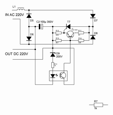
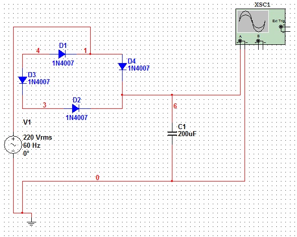
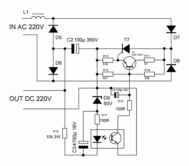
Hi, can anyone give me a schematic or suggest a way of how to convert 220AC to 220DC. We will use the 220DC as a supply for a motor in our project.

Is it possible not to use a transformer?

Help is very much appreciated!
 

Probably. What power/current is needed to operate your motor and how critical is the voltage stability?

Brian.
 
for the motor, the current needs 2A. With respect to voltage stability... well.. i have to get back at you..
 

i can't help you with a schematic but my approach would be a bridge rectifier to convert the AC to DC, followed by a phase controlled SCR to regulate the voltage. That would happily supply 2A and should be good for a brief burst at much higher current as the motor starts up. Depending on the motor characteristics, you may need to use a capacitor across the DC to reduce voltage ripple.

Brian.
 

a bridge rectifier will convert from ac to dc and what type of motor you are using that is not clear
 

may be do like that

however for usual engine single bridge rectifier will be enough.
 
Last edited:

For general dc-motor you can use only diode bridge
without filter condensator.
For control use normal triac controller ( light dimmer or motor controller )

Look picture.....................

View attachment 220ac_dc.pdf
 
  • Like
Reactions: ypming

    ypming

    Points: 2
    Helpful Answer Positive Rating
Thanks for the tip, um what do you mean by "Phase Controlled SCR" do you have a schematic for that? Thanks!

---------- Post added at 14:06 ---------- Previous post was at 13:56 ----------

Hi Guys, i tried a circuit. the problem is it reaches 310VDC how can i reduce that


Yes, the unchancy design. But it works with some improvement.

However obtain good functioning of this scheme by way of the increase capacity is a dead-end way.
 
Last edited:
Like Syncopator said : remove the capacitor.

Then you can count the value Vrms = Vin (bridge)
Irms = Ipeak * 0.707

Look my picture 220ac_dc

Regards KAK
 
  • Like
Reactions: ypming

    ypming

    Points: 2
    Helpful Answer Positive Rating
Hi guys, we used a 1n4007 diode and they burned out... a friend told me to use a "Power Diode", is there a particular diode that i should use for this application? Thanks!
 

Diode 1N4007 is only for current smaller than 1Amp.

Normally starting motor well need current like 5...10 times Inom.
(= current value in motor data plate )
This starting current varies for different motor types .

I suggest you to use 25A 600V diode bridge ( or even 35A 600V)
They have relatively low price.
Ask your dealer general diode bridge for those values ,
price should be about 5$.

Without knowing your motor type, it is wise to connect
one diode parallel to motor anode to bridge plus and cathode to
bridge minus for killing voltage spikes from motor. ( 3A 600...800V)
( must, if your motor have brushed type.)
(Or use so called spark killer RC circuit for 600 volts )
And dont forget put the fuse before your diode bridge.

Regards KAK
 
  • Like
Reactions: ypming

    ypming

    Points: 2
    Helpful Answer Positive Rating
Status
Not open for further replies.

Part and Inventory Search

Welcome to EDABoard.com

Sponsor

Back
Top