Continue to Site

Welcome to EDAboard.com

Welcome to our site! EDAboard.com is an international Electronics Discussion Forum focused on EDA software, circuits, schematics, books, theory, papers, asic, pld, 8051, DSP, Network, RF, Analog Design, PCB, Service Manuals... and a whole lot more! To participate you need to register. Registration is free. Click here to register now.

3bit cmos encoder cicuit

Status
Not open for further replies.

Aritra17

Junior Member level 3
Joined
Feb 20, 2011
Messages
30
Helped
4
Reputation
8
Reaction score
2
Trophy points
1,298
Location
kolkata
Activity points
1,610
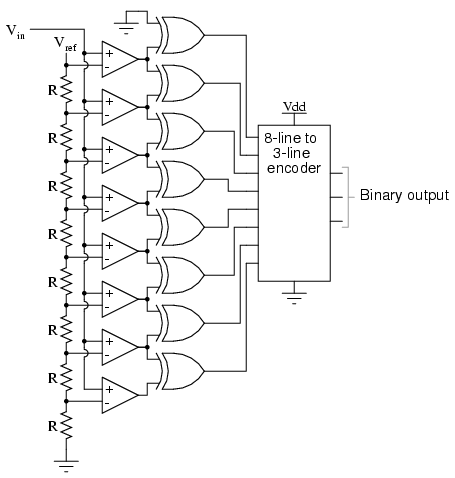
i need a 3 bit cmos encoder circuit with all the 8 inputs
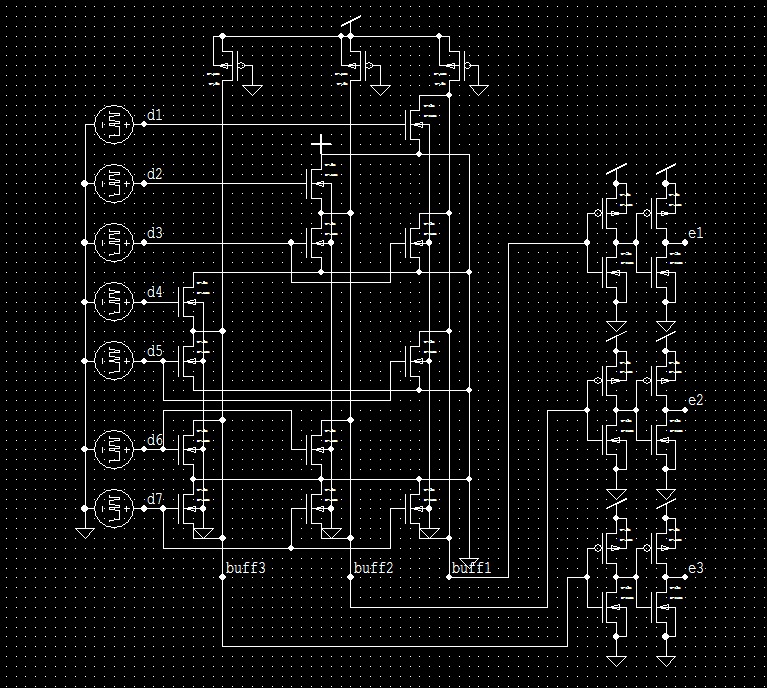
i have created a 7 input encoder using rom design bt i need to have the '000' condition also
please help
 

What about a 3-input NOR ?
 
  • Like
Reactions: kiio

    kiio

    Points: 2
    Helpful Answer Positive Rating
i need a encoder
why would i need to think about a nor??
its very simple
just add 2 nor with one another in series
 

i can't understand what you r trying to say
how is that possible to create a 3bit encoder using 3input nor??
2 nor joined in series means the relation is like this:
((a+b)bar +c)bar
if i consider a=1 & rest 0 then the result is 1
same thing happens for b
but in case of c when it is 1 and rest 0 then the result is 0
which is incorrect in terms of encoder

and secondly this happens for 3 inputs & one out put
i need 8 inputs & 3 outputs
how am i supposed to join these nor gates??

if you can explain in details with a circuit diagram that would be helpful
i can't understand this way
 

i can't understand what you r trying to say
how is that possible to create a 3bit encoder using 3input nor??

Hi Paul,
in your original question (above) you asked
... bt i need to have the '000' condition also
please help

... so I just wanted to give you a hint how to master the '000' condition, but erroneously I thought of decoding (3 to 8 ) instead of encoding (8 to 3), sorry!

2 nor joined in series means the relation is like this:
((a+b)bar +c)bar
if i consider a=1 & rest 0 then the result is 1
same thing happens for b
but in case of c when it is 1 and rest 0 then the result is 0
which is incorrect in terms of encoder

So you found out that this wouldn't work! That's what I wanted to tell you above. Still thinking of decoding.

... and secondly this happens for 3 inputs & one out put

No: for decoding the '000' condition a 3-input NOR would work (output high in this case).

i need 8 inputs & 3 outputs
how am i supposed to join these nor gates??

For encoding the '000' condition (only) you'd need an 8-input NOR gate e.g. like MC14078B or 6x2-input OR + 1x2-input NOR (for active high output).

Schematics for a full 3 to 8 encoder can easily be found via G00gle images search.
 

For encoding the '000' condition (only) you'd need an 8-input NOR gate e.g. like MC14078B or 6x2-input OR + 1x2-input NOR (for active high output).

couldn't understand what you tried to explain
if i use 6 two input or gates the number of inputs will be 8 i agree
but how will it end up having only 3 outputs????

and i need the full encoder with all the 8 input conditions
i.e '000' condition to '111' condition

google image search does not give 8 to 3 bit encoder
not in cmos schematic level

actually im making a 3 bit adc circuit in tanner eda software
i have created all of the basic components
i have also created a encoder for the circuit but its giving some abnormality
you can see that abnormal behavior of the output waveform in another thread of mine
named as "output waveform of a 3bit flash adc in tanner eda software"

the encoder i built using cmos schematic has 7 inputs & has 7 high-low conditions in the output waveform
but i don't think think that's right
that's why i need help

please understand the full condition
and please help
 

google image search does not give 8 to 3 bit encoder
not in cmos schematic level

Try this G00gle request. Already the first row shows appropriate schematics:
79_1300713497.gif
 

where does the I0 input goes to?

Nowhere, as you can see. It's unused.

I<7:0>, representing the numbers 0..7 , are encoded to a binary (resp. BCD) representation of the respective number.

The '000' condition is already covered by the 3 OR gates: if I<7:1> = 0 --> Y=0 , no matter if I<0> is set (which it should be, if the input is non-ambiguous) - or not.
 

see i know this condition
i told you before also
i need all the 8 input conditions '000' up to '111'
my encoder has 7 input terminals and also shows 7 high low conditions but i need to have 8 high low conditions using cmos technology

your given circuit seems to be made through vldl programing

i am using tanner eda software

please try to give me a 8 input 3 output cmos encoder
 

The above circuit exactly fulfills the function of your "8-line to 3-line encoder" box.

A 3-bit binary output can only represent the numbers 0..7, and not 1..8 . In your above schematic, if your Vin is either below the ref. voltage of the bottom-most comparator (then its output is low), or if Vin is between the ref. voltages of the 2 bottom-most comparators (in this case the output of the bottom-most comparator is high), in both cases the '000' condition is encoded, hence the output state of this comparator (I<0>) is irrelevant, and both the bottom-most comparator and EXOR are dispensable - like the top-most EXOR, BTW.

If you don't want to loose the bottom-most half-bit, I'd suggest to change your circuit to the following one.
With this, you can save one comparator and 2 EXORs:

68_1300797481.png
 

this is the encode circuit


and this is my flash adc 3 bit output waveform


please tell what should be the desired output
 

Status
Not open for further replies.

Similar threads

Part and Inventory Search

Welcome to EDABoard.com

Sponsor

Back
Top