Continue to Site

Welcome to EDAboard.com

Welcome to our site! EDAboard.com is an international Electronics Discussion Forum focused on EDA software, circuits, schematics, books, theory, papers, asic, pld, 8051, DSP, Network, RF, Analog Design, PCB, Service Manuals... and a whole lot more! To participate you need to register. Registration is free. Click here to register now.

200MHz bandwidth filter design

Status
Not open for further replies.

adnan012

Advanced Member level 1
Joined
Oct 6, 2006
Messages
468
Helped
2
Reputation
4
Reaction score
2
Trophy points
1,298
Activity points
4,923
hi,

I want to design a 200MHZ bandwidth filter with center frequency of 800MHz using Lumped components. i need sharp cutoff response for that filter. Is it possible to construct this filter using lumped elements , accurately . I have tried my best to implement this filter with the help of ads simulation , but it never works on prototype for full bandwidth, i achieved only 75 MHz bandwidth.

I have small collection of rf inductors and capacitors.

inductors 0.4 nH, 0.7 nH , 1.2 nH............. up to 50 nH
capacitors 0.1pF, 0.2pF, 0.5pF................... up to 50pF

Is there any solution for my problem.
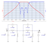
 

I'm not an rf expert, but I would guess that you've got some parasitic reactances that are not being taken into account. How are you prototyping this? Your bw is off, but what about your cutoff frequency, is that correct?
 

Here are some values you can use as a starting point.
 

Attachments

  • 800M-BPF.gif
    800M-BPF.gif
    57.7 KB · Views: 95
What you have to be careful about it to find lumped element components with high enough Q. Capacitors are readily available with high Q if you order carefully, but inductors are another story. A lot of people wind their own inductors on miniature toroids to get a high enough Q value.

The other problem is tuning....chip components have only one value, and that value varies +/- over a tolerance range. So often you need to add some tuning element (like a small trip cap tuned with a screwdriver) or splitting the capacitor values up into 2 pieces: for 22 pF...you choose a 20 pf and a 2.0 pF. That way you can change the 2 pf to 1.8, 1.5, 2.2, 2.5 pf, etc.
 

If you are able to get Murata's inductor and capacitor design kit ( for instance LQP series inductors and GRM series capacitors) you'll find the values which are necessary for your design.Filter design needs proper and precise values of caps. and inds.Of course PCB is also very improtant.
And input and output connectors,grounding,transmission lines etc..
You should consider all of those physical circuit parameters properly and design your circuit carefully with precise components.
 

There can be a lot of things that you are not taking in to account or not informing us about.
But here is a quick way to see if you are just missing a factor in your calculations.

You designed for BW = 200 MHz, but got only 75 MHz.
Well just design for ~ 320 MHz and see if that gets you to 200MHz.

You many not have got the right "er" or used "f" instead of "ω".

Hope this helps one way or another.

P.S. you should go back and put in values that exist and not the optimal values.
 

Status
Not open for further replies.

Part and Inventory Search

Welcome to EDABoard.com

Sponsor

Back
Top