BlackMelon
Newbie level 4
Hello,
In an arc welder, there is the converter like this:
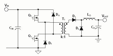
For its driving system, there are two driving systems, which are the same but completely isolated from each other to apply driving signals to the gate and the source of each power mosfet
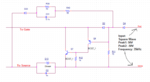
My question, according to the attached picture, is:
1. How does this group of components function ?
2. Is it ok to remove these components and apply the square wave directly to the gate and source of each power mosfets presented in the link?
Thank you
BlackMelon
In an arc welder, there is the converter like this:
For its driving system, there are two driving systems, which are the same but completely isolated from each other to apply driving signals to the gate and the source of each power mosfet
My question, according to the attached picture, is:
1. How does this group of components function ?
2. Is it ok to remove these components and apply the square wave directly to the gate and source of each power mosfets presented in the link?
Thank you
BlackMelon
Attachments
Last edited by a moderator: