DoYouLinux
Advanced Member level 4
Hi all,
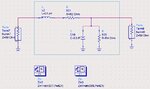
I am wondering about a simple thing. In ADS, I have a lumped network consisting of a series branch (L and R) and a shunt branch (C and R), as shown in the attached figure. If I want to measure the impedance between both terminals of this lumped network, how should I proceed ? Clearly, I cannot ground the terminal at the shunt branch because this will eliminate the shunt branch.
Is there any building block in ADS that allows me to get a 2-terminal impedance like this network ? I need to extract this impedance to be used in a MeaEqn.
It seems that "Zin" block is not for floating impedance like this one, it should be for measuring impedance of a grounded network.
I should figure out how to do, but it seems not clear to me now.
Please suggest :wink:
DYL