Continue to Site

Welcome to EDAboard.com

Welcome to our site! EDAboard.com is an international Electronics Discussion Forum focused on EDA software, circuits, schematics, books, theory, papers, asic, pld, 8051, DSP, Network, RF, Analog Design, PCB, Service Manuals... and a whole lot more! To participate you need to register. Registration is free. Click here to register now.

2 loopsticks as a omnidirectional array

Status
Not open for further replies.

dr pepper

Advanced Member level 1
Joined
Mar 15, 2010
Messages
420
Helped
34
Reputation
68
Reaction score
40
Trophy points
1,308
Location
lancs
Activity points
4,128
I want to prototype an omnidirectional magnetic loopstick ant.
I cannot find much data on the web, maybe I'm not using the right search strings.
Anyway what is a good way to do this, my initial idea is to buffer 2 loopsticks orientated at 90 degrees with 2 fets, then mix the o/p of the fets using 2 windings on a 4 winding balun the third winding of which feeds the rx, the last winding on the balun for tuning connected up to a variable cap.
Or is there a easier idea.

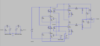
EDIT: Ok I threw this together,
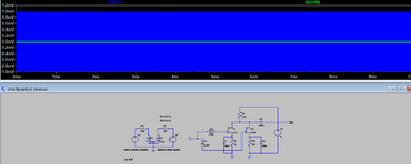
2 fets add the 2 loopstick signals, with a little gain, in order to get the 'signal' into the loopsticks I made them into transformers with the circuit on the left providing excitation, varying the amplitudes of the sources to crudely change the transmitter direction, seems to work.
In real life there might be some weird cancellation issues.
 

Attachments

  • omni ant circuit.png
    omni ant circuit.png
    17.2 KB · Views: 89
Last edited:

In real life there might be some weird cancellation issues.
Good guess. Adding the signals of two 90° oriented coils creates a 45° rotated dipole characteristic. A simple approach for omnidirectionality would be a 90° phase shift network.
 

Even if I made an all pass filter I'd probably have trouble keeping it aligned.
Any recommendations for an omnidirectional loop for am broadcast?
I'm resisting the silly idea of an arduino and a servo.
 

Differential 90° phase shift can be achieved over multiple decades, a standard technique in SSB modulators/demodulators.

As for the omnidirectional loop, think about magnetic field polarizations and the loop orientations to receive it. A vertical polarized field can be received with an omnidirectional horizontal loop, but there's no omidirectional antenna for a horizontal polarized E or H field.
for the vertical part, you can also just use a quarterwave whip antenna

so an omnidirectional loop with a vertical whip pointing up from the middle
 

Wasnt there an rdf antenna that used a loop and a whip to remove one of the directional lobes?
At low freq's however the whip would be huge.
A loop works well, an active whip works but is noisy.
I guess another alternative is to have 2 loops with 2 receiver front ends and some kind of diversity switching based on sig strength.

Edit: I threw this together to see if I could make a simple diversity front end, L1/3 are the loopsticks, they are amplified by a single IF stage, then compared to see which is the strongest signal, that being the one that gets switched through to the final iF.
The circuit needs some more fiddling, plus I used to have an fm diversity receiver, it was a pain when it kept switching, so its probably not a good idea.
 

Attachments

  • crop.png
    crop.png
    27 KB · Views: 83
Last edited:

Status
Not open for further replies.

Part and Inventory Search

Welcome to EDABoard.com

Sponsor

Back
Top