Continue to Site

Welcome to EDAboard.com

Welcome to our site! EDAboard.com is an international Electronics Discussion Forum focused on EDA software, circuits, schematics, books, theory, papers, asic, pld, 8051, DSP, Network, RF, Analog Design, PCB, Service Manuals... and a whole lot more! To participate you need to register. Registration is free. Click here to register now.

2 flag pull interface

Status
Not open for further replies.

keyboardcowboy

Member level 2
Joined
Mar 4, 2010
Messages
42
Helped
0
Reputation
0
Reaction score
0
Trophy points
1,286
Activity points
1,612
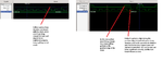
I am implementing an arithmetic block with a 2 flag pull interface. Random numbers from a test bench are pushed into this block with a 2 bit command which instructs the block what operation is to be performed on the input. I am done implementing all the functions, but I am stuck at the output interface of the block. The output is a 2 flag pull interface, the testbench can request data at any time. The 2 pull signals are "pullout" and "stopout". If the testbench issues a pullout signal then I am suppose to output result with stopout 0, otherwise stopout is one. The problem is that pullout can be of any duration, and when the pullout is high I have to provide the result and stopout 0 signal before it goes low. Please see the attached image for more clear picture.
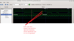
In the image when the pullout goes high, I provide the result on the next positive edge of the clock but by that time pullout has gone low, and the output result is not considered, and i get an error message. I am required to use sequential, and synthesizable verilog.
 

Attachments

  • upload.png
    upload.png
    47.9 KB · Views: 63

hi,

when ever the pull out is high, stopout must be low right???(according to you)

here only once stopout gone low . why ?

regards
 

The arithmetic operations are pipelined, into 114 stages, stopout only goes low if pullout is high and there is valid data to give, here it has gone low once because there was only one valid data available at that time
 

Maybe you should provide the desired behavior of the signals pullout and stopout in a drawing, instead of the wrong simulation output your current implementation is giving. I'm not entirely sure what your requirements for the two signals are.

Even though I can't be sure from you description...

If what you want is the pullout == 1 and the stopout == 0 when there is valid data then you could do something like this:


Code Verilog - [expand]
1
2
// assuming there is a data valid that is high with the output data is valid.
assign stopout = ~(pullout & valid);


The pullout signal is generated by the testbench, it can be high at any time, and of any duration. It is not in sync with the clock. Please check the attached images. I also tried the valid technique, but that too didn't work
 

Attachments

  • upload2.png
    upload2.png
    65 KB · Views: 60
  • upload3.png
    upload3.png
    103.5 KB · Views: 61

I'm getting the impression that pullout is an asynchronous input to your logic and you are not synchronizing it.

Plus you may have testbench issues which are causing weird looking delta time simulation issues, resulting in glitches in your stopout signal.

You're specification of what you require is still not entirely clear. Is there a 1-to-1 correspondence between a pullout pulse (of any duration) and a single stopout going low for one clock cycle when there is valid data?

Who wrote the specification on how this pullout/stopout is supposed to work? It's a really lousy interface transfer protocol.

yes, there is a correspondence between pullout and stopout pulse, but only when I have valid data to output. If I have valid data then whenever there is a pullout I am suppose to output data with stopout 0 for one clock. I am not synchronizing pullout. do i need to do that?. The same test bench has been successfully passed by someone else so that means there is no problem with the testbench
 

yes, there is a correspondence between pullout and stopout pulse, but only when I have valid data to output. If I have valid data then whenever there is a pullout I am suppose to output data with stopout 0 for one clock.
So it doesn't mater how long pullout persists you generate a stopout? e.g. pullout is 100 sec long you generate a single stopout, e.g.2. pullout is 1 fs long you generate a single stopout.

I am not synchronizing pullout. do i need to do that?.
Seriously, what do schools teach engineering students? Yes of course you synchronize. You are trying to use a signal that is asynchronous to the clock you are running your logic with. If you don't synchronize pullout you may end up with a metastable event on the FFs that use the pullout signal.

The same test bench has been successfully passed by someone else so that means there is no problem with the testbench
Yeah, famous last words...I would be highly suspicious of any testbench someone else gave me until I've analyzed it.
 

Status
Not open for further replies.

Part and Inventory Search

Welcome to EDABoard.com

Sponsor

Back
Top