Continue to Site

Welcome to EDAboard.com

Welcome to our site! EDAboard.com is an international Electronics Discussion Forum focused on EDA software, circuits, schematics, books, theory, papers, asic, pld, 8051, DSP, Network, RF, Analog Design, PCB, Service Manuals... and a whole lot more! To participate you need to register. Registration is free. Click here to register now.

2 BLDC Motor Controller design

Status
Not open for further replies.

Veja

Newbie
Joined
Feb 19, 2021
Messages
3
Helped
0
Reputation
0
Reaction score
0
Trophy points
1
Activity points
54
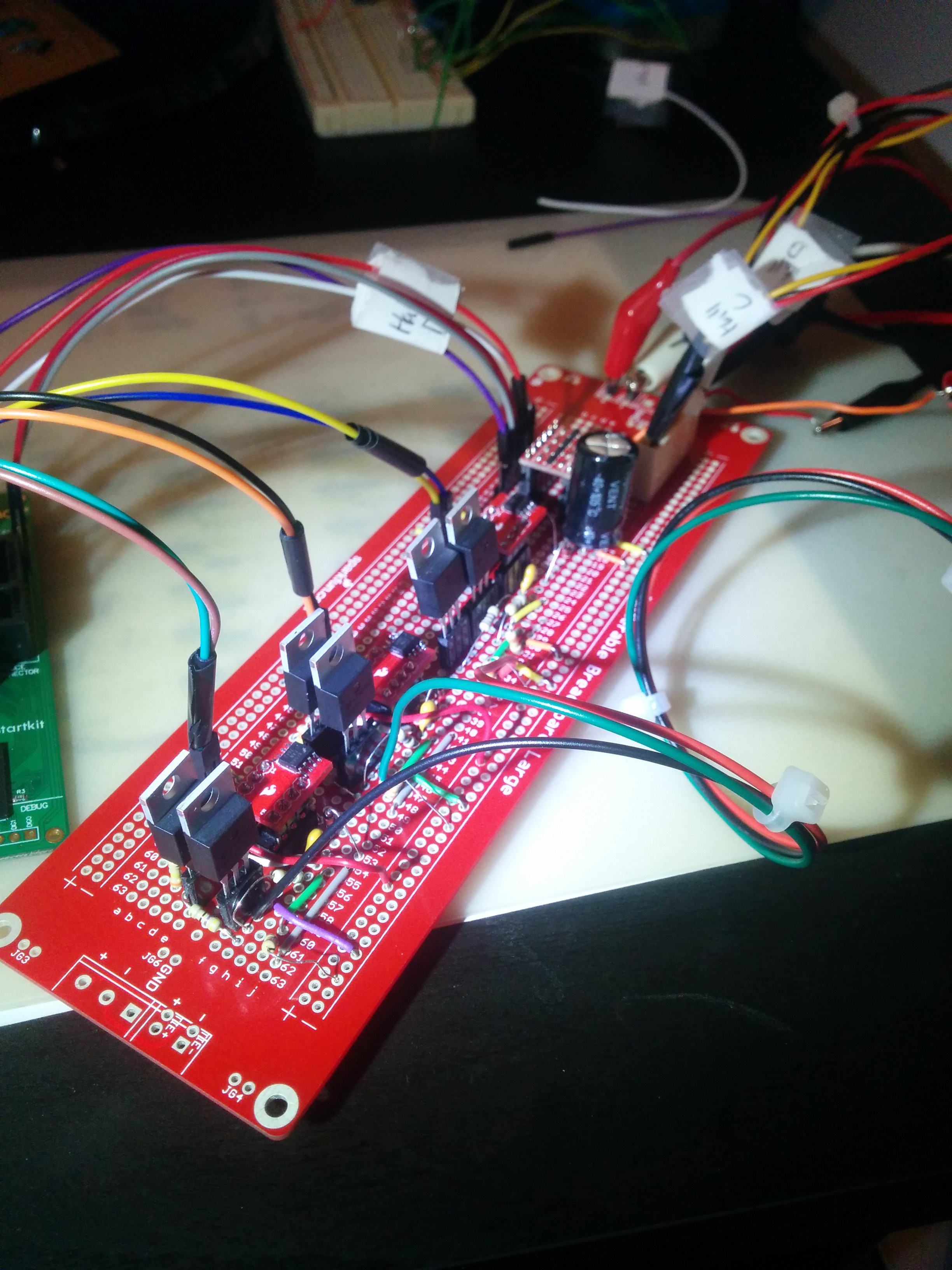
Hi, I am electrical engineering student doing my final year project which is design of a BLDC Motor Controller that can control two BLDC motors at the same time in an axel. I am also using 24V BLDC motor from RS components as shown in the attachments, I have STM32 F446RE as my main controller and I will be using IR2110BPF as mosfet drivers which will drive IRF540N n-channel mosfet. for both low and high side.
I will kindly appreciate anyone assist on this, at least share your previous project schematics and guide if you willing or you can guide me on how to go about from the forum.
Thank You!
 

Attachments

  • 0900766b81580e4a.pdf
    595.6 KB · Views: 142

Hi,

What's the goal?
Controlling them totally independently? Or combined somehow, or only one at a time?
Just controlling ... or some regulation loop? RPM, torque, power....?
What RPM range?
What control scheme?

Basically for simple control you just need a couple of signals from microcontroller to the IR2110.
And there are plenty of example designs, schemtics, code, design notes....
What's wrong with them? Why do you need another one?

Klaus
 

    Veja

    Points: 2
    Helpful Answer Positive Rating
Dead time control of PWMs crucial in driving totem pole low/high side
MOSFET circuits -

Google "dead time pwm bldc"


Circuits layout, due to fast high currents involved, crucial for processor reliability -

**broken link removed**

**broken link removed**


**broken link removed**


Regards, Dana.
 

    Veja

    Points: 2
    Helpful Answer Positive Rating
Hi,

What's the goal?
Controlling them totally independently? Or combined somehow, or only one at a time?
Just controlling ... or some regulation loop? RPM, torque, power....?
What RPM range?
What control scheme?

Basically for simple control you just need a couple of signals from microcontroller to the IR2110.
And there are plenty of example designs, schemtics, code, design notes....
What's wrong with them? Why do you need another one?

Klaus
Hey Klaus thank you for your reply. In short, the motors are to be controlled simultaneously, meaning they must be able to run at same speed if possible, under sophisticated control technique such as PID, that means it should be close loop system, were I be only feeding back the speed for both motors to PID control mode which I would implement it on software platform using STM32-F446RE microcontroller.
  • I only need to design a prototype for the project, and display motor phase currents measurements and speed correction for both motors using PID in RPM.
  • Implement forward, reverse and braking features.
  • I don't want use a complex control scheme, I want implement 6 Step communication scheme because of it's simplicity and I have limited to time complete the project.
  • The motors are rated at 4000 RPM according to the datasheet below, and they are sensored. So I must be able to run them from minimum speed and close to their rated maximum speed if possible.
  • Current or Torque correction are not to be incorporated but I should display the motor currents.
  • I terms of hardware, I am thinking to use IR2110 drives because they are commonly used to drive the MOSFETs in BLDC Motor Control and because MCU doesn't provide enough voltage to to fully turn-on the MOSFET's and I will be including some isolation circuitry such opto-isolators from the MCU.
The above features will be enough for me to control, and I have gone through most of the project report, design examples and schematics online but they only provide a control for one BLDC Motor for almost all of them, and if I happen to get hold of design that is a bit similar to mine, their to complex and requires great amount time and capital. My most concern around is that, if I have to control them both as stipulate above:
  • Should they be controlled in parallel or separate with separate drivers from the same MCU signals?
  • What are other things I should take in consideration if I have to control them both so I can able to run them in a effective manner.

I know I am asking too much, the reason is I have basic knowledge around electronics, power electronics and software programming but I am willing to take try on this for my final year project, so I would appreciate your insight or anyone else in that matter.

Thank You.
 

Dead time control of PWMs crucial in driving totem pole low/high side
MOSFET circuits -

Google "dead time pwm bldc"


Circuits layout, due to fast high currents involved, crucial for processor reliability -

**broken link removed**

**broken link removed**


**broken link removed**


Regards, Dana.
Thanks Dana for the information provided, actually I have been having some struggle lately on that concept for PWM signaling and deadtime concept, and now that you have given me some reference websites, they will be more helpful towards my design implementation.
 

The extra HW, all available onchip, would be trivial to add for second motor.
Here is example for one motor, as you can see from right hand window
resources used/left many more available. And this is low end chip, easy to
use the 5LP family for much greater resources. Add a mux to the SAR, and
anolther LUT, Another DAC and Comparator, and misc logic gates, all onchip
for second motor

The board to use is $ 10, or the complete kit (which I don't think you need) -

If you use the basic board you will need the power stage for the motor,
thats not onchip. Those of course these days pretty cheap.

Reference design: supports simple to advanced BLDC motor implementations; including
FOC (Field Oriented Control), sensored and sensorless BLDC motor control implementation

1614300588014.png


Compiler and IDE , PSOC Creator, free.


Regards, Dana.
 

Even if you intend to make your own driver circuitry with the IR2110, I'd highly recommend starting out using a good off-the-shelf driver stage with protections built in. Otherwise you're likely going to be destroying your hardware frequently while debugging your code.

Something like this: https://www.monolithicpower.com/en/ev6530-f-00a.html
 

Status
Not open for further replies.

Similar threads

Part and Inventory Search

Welcome to EDABoard.com

Sponsor

Back
Top