Continue to Site

Welcome to EDAboard.com

Welcome to our site! EDAboard.com is an international Electronics Discussion Forum focused on EDA software, circuits, schematics, books, theory, papers, asic, pld, 8051, DSP, Network, RF, Analog Design, PCB, Service Manuals... and a whole lot more! To participate you need to register. Registration is free. Click here to register now.

2.5 GHz Filter design using Transmission lines.

Status
Not open for further replies.

ayaaz_350

Newbie level 1
Joined
Feb 4, 2011
Messages
1
Helped
0
Reputation
0
Reaction score
0
Trophy points
1,281
Activity points
1,293
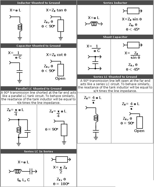
I am designing a 2.5 GHz Band Pass Filter. According to what i understand that this frequency is too high for lumped components and therefore i have to use transmission lines. I have obtained a circuit for 2.5 GHz BPF using lumped components what i now need is to design this filter using transmission lines. Can i convert the Lumped component circuit to a transmission line circuit?

Thanks alot for having a look at my post please do reply if you know the solution to my question.

Thank you.
 

The attachment gives you some information about this conversion.

 
You have many choices to make a filter at 2.5 GHz, depending on your requirements, such as bandwidth, rejection, and insertion loss, etc. People do make LC filters at 2.5 GHz. Actually, it is easy to make LC filters at 5 GHz. Some people even make LC filters at 8 GHz. Some other common choices are ceramic filters, combline filters, microstrip filters, etc.

Good luck with your design.
 

Hmmm....LC filters at 8GHz?
Using lumped inductors and capacitors in pico-Henry and femto-Farad range, most probably if you open the window the center frequency will move hundreds of MHz.
 

The easiest method is to determine the impedance of each stage from the ideal lumped. The ideal filter has series LC pair and shut parallel LC alternating. The impedance of the LC pairs is sqrt(L/C). That is the easy part, there are many way to implement in a printed circuit. The series impedances can be a thin line but it is hard to get more than 200 Ohms, also high impedance lines are difficult to make and radiate. The shunt LC will have low impedance and this can be made with a fat stub to ground. The problem here is if the stub impedance is less that say 10 Ohms, it starts to look like distributed circuits. There are tricks to making this work but it take years of practice to know thm all.

I would start by converting all the series high impedances to shunt low impedances with 1/4 wave Z0 TL lines. Then try to make all the stubs work. I hope you have a 2.5D modeler to see if the stubs have the correct impedance.

Good luck
 

I would be curious to see any examples of lumped filters at 8 Ghz. Are you talking about mmic chips with a simple filter on them, or actual pc boards with lumped chips on top?
 

Maybe dielectric filter is better choice than trans line. For trans line filter, you should think the box to get your designed performance.
 

Status
Not open for further replies.

Part and Inventory Search

Welcome to EDABoard.com

Sponsor

Back
Top