Continue to Site

Welcome to EDAboard.com

Welcome to our site! EDAboard.com is an international Electronics Discussion Forum focused on EDA software, circuits, schematics, books, theory, papers, asic, pld, 8051, DSP, Network, RF, Analog Design, PCB, Service Manuals... and a whole lot more! To participate you need to register. Registration is free. Click here to register now.

1mA current source using LM 134

Status
Not open for further replies.

engr_joni_ee

Advanced Member level 3
Joined
Nov 3, 2018
Messages
744
Helped
2
Reputation
4
Reaction score
4
Trophy points
18
Activity points
6,191
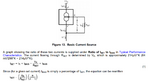
Hi, I need to design 1mA current source for PT1000. I just have found LM 134 adjustable current source. I have some questions, if V+(+VIn) is powered up by 5 V then how do I know about VR across RSET ? see attachment. What is the value of RSET and VR do I need to put in Eq (1) that gives ISET = 1 mA ?

If I get 1 mA through LM 134 with correct values of REST and VR then I guess PT1000 should be connected with ISET and the other terminal of PT1000 has to be connected to GND, right ? At temperature 0 C, the PT1000 will have 1000 Ohm and 1 mA through the PT1000 will give 1 V across PT1000 at 0 C that will change with temperature.
 

Attachments

  • Untitled.png
    Untitled.png
    139.3 KB · Views: 378
Last edited:

You need to look at T compensated design -


1610549710878.png


Vr is a reference V, but has a T dependency that you have to compensate for
if you want T independent accuracy -

1610549973085.png


Your PT1000 would be connected in series with above circuit.


If you are using PT1000 with a processor that can help with design errors. Here is one
example of many on web - (this is a single chip design, PT1000 external of course)


1610550444407.png


Regards, Dana.
 
Last edited:
You need to look at T compensated design -


View attachment 166920

Vr is a reference V, but has a T dependency that you have to compensate for
if you want T independent accuracy -

View attachment 166921

Your PT1000 would be connected in series with above circuit.


If you are using PT1000 with a processor that can help with design errors. Here is one
example of many on web - (this is a single chip design, PT1000 external of course)


View attachment 166923


Regards, Dana.

Regarding accuracy, 0.5 C should be fine for my measurement and the temperature range is -100 C to 200 C.

If PT1000 is connected in series to ISET and the other terminal of PT1000 connected to GND. If PT1000 is located inside the thermal chamber and the rest of electronics is placed at standard lab temperature then do I also need to compensate for VR ? I guess not.

If I get 1 mA in ISET that run through PT1000 inside the thermal chamber then at temperature 0 C, the PT1000 will have 1000 Ohm resistance and 1 mA through the PT1000 will give 1 V across PT1000 at 0 C. Is that correct ? If temperature inside the thermal chamber is change, it will change the resistance of PT1000 that will change the voltage across PT1000 which will be readout by microcontroller.

1) Yes, OK not to use T compensation if your design accuracy goals met. But that means you
do a total signal and device path error analysis, otherwise you are fooling yourself.

2) Yes, 1 mA thru 1K ohms = 1V.

You do have some wire drop, and its tempco, again a complete error budget always a good
idea.

.5C, the T depoendence of set current is -

1610579744165.png


1610580251660.png


Set current error is at room temp....

basically +/- 4%, so at room temp thats +/- 4% error, and that does not include the other errors.

If this is a one off you can always to a ice bath cal of the LM134 with a trim to take out error.

Lastly you may have a problem with common mode error if not using differential V measurement
of PT1000. In light of facts its a furnace, lots of power cycling in its temp controller creating noise.

Don't forget you have to keep the LM134 in compliance to keep it regulating, note this in spec sheet is
just room temp value -

1610580955726.png


Regards, Dana.
 
Last edited:


If PT1000 is located inside the thermal chamber and the rest of electronics is placed at standard lab temperature then do I also need to compensate for VR ? I guess not.
Vr has similar t.c. as Pt1000 resistance. If you are using LM134 without compensation, the circuit temperature variation must be kept below 0.5 K to achieve your accuracy requirements. No realistic idea.
 

Status
Not open for further replies.

Similar threads

Part and Inventory Search

Welcome to EDABoard.com

Sponsor

Back
Top