Tahmid
Advanced Member level 6
- Joined
- Jun 17, 2008
- Messages
- 4,756
- Helped
- 1,798
- Reputation
- 3,588
- Reaction score
- 1,656
- Trophy points
- 1,413
- Location
- Berkeley, California
- Activity points
- 30,583
Hi all,
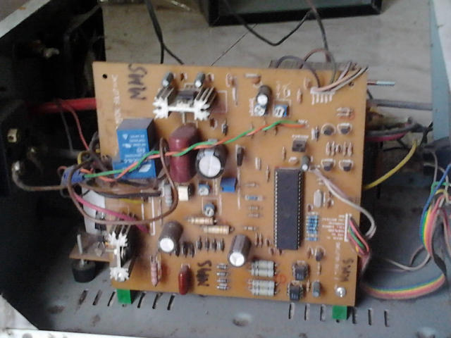
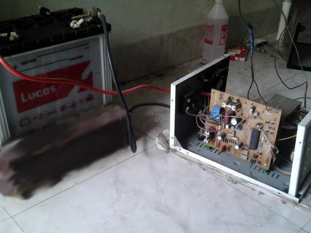
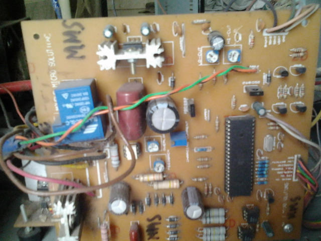
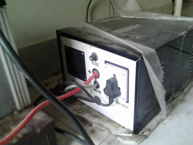
rajudp and sahu wanted to see pics of my inverter that I mentioned earlier in another post, so here it is. For the benefit of the members, I describe the circuit as:
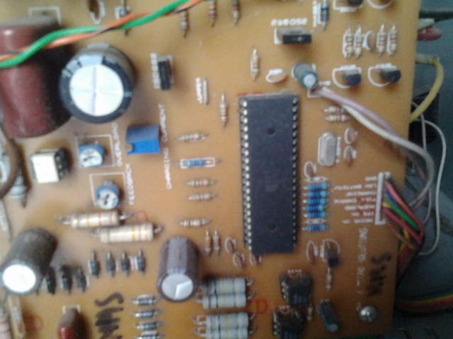
*single microcontroller/controller (ATMEGA16/32)
*no op-amps, only chips are the micro, opto-couplers and regulator (7805)
*low-battery/overload/short-circuit protection
*thyristor controlled battery charger, using the MOSFET body diode as the AC-DC rectifier
*charger maintains the battery voltage (top) between 13.2-13.5v (adjustable) to maximize the battery life
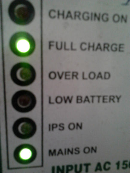
*6-LED display
*Only 93 parts in entire control circuit
*Delay between switchover to prevent inrush current
The method used here, described for those who may benefit from it:
-Initialize all ports and peripherals[ADC, Timers, Compare Modules]
-Initialize interrupts for Timer0 and compare module for
-For PWM, use Timer1 and 16-bit Phase and Frequency Correct PWM mode so the PWM runs completely on the hardware level without need for interaction to keep it running
-The AVR senses whether mains is present or not using a standard opto (4N35).
-If mains present, check battery level
-If battery level < 13.5v (this voltage is set using a pot, so can be easily adjusted), charge at the set current(set with a pot)
-If battery level > 13.5v, stop charging
-While battery > 13.2v, stop charging
-If battery voltage drops instantly start charging again
-Triac based, uses Timer0 and compare module with interrupt for phase angle control for fast charge, never overcharges battery, battery hasn't ever heated up till now and 2 year old battery still gives good backup, so charging algorithm is good for battery life
-Check mains
-If mains absent, initialize Timer and start PWM
-Check battery voltage, stop PWM and indicate on LED when battery falls below 10.8v (this is also set with a pot), response time is fast so a short circuit that produces an instant voltage drop is detected
-Check load level, check against preset level (set with pot) and if too high, shut down and indicate
-Check output voltage, adjust as required
-Check mains
*Coding is done with mikroBASIC PRO for AVR
*All voltages mentioned, eg 13.2v, 13.5v, 10.8v, Overload voltage, etc are all adjustable and set with variable resistors
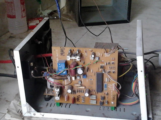
I will upload the schematic and PCB design soon.
Tahmid.
rajudp and sahu wanted to see pics of my inverter that I mentioned earlier in another post, so here it is. For the benefit of the members, I describe the circuit as:
*single microcontroller/controller (ATMEGA16/32)
*no op-amps, only chips are the micro, opto-couplers and regulator (7805)
*low-battery/overload/short-circuit protection
*thyristor controlled battery charger, using the MOSFET body diode as the AC-DC rectifier
*charger maintains the battery voltage (top) between 13.2-13.5v (adjustable) to maximize the battery life
*6-LED display
*Only 93 parts in entire control circuit
*Delay between switchover to prevent inrush current
The method used here, described for those who may benefit from it:
-Initialize all ports and peripherals[ADC, Timers, Compare Modules]
-Initialize interrupts for Timer0 and compare module for
-For PWM, use Timer1 and 16-bit Phase and Frequency Correct PWM mode so the PWM runs completely on the hardware level without need for interaction to keep it running
-The AVR senses whether mains is present or not using a standard opto (4N35).
-If mains present, check battery level
-If battery level < 13.5v (this voltage is set using a pot, so can be easily adjusted), charge at the set current(set with a pot)
-If battery level > 13.5v, stop charging
-While battery > 13.2v, stop charging
-If battery voltage drops instantly start charging again
-Triac based, uses Timer0 and compare module with interrupt for phase angle control for fast charge, never overcharges battery, battery hasn't ever heated up till now and 2 year old battery still gives good backup, so charging algorithm is good for battery life
-Check mains
-If mains absent, initialize Timer and start PWM
-Check battery voltage, stop PWM and indicate on LED when battery falls below 10.8v (this is also set with a pot), response time is fast so a short circuit that produces an instant voltage drop is detected
-Check load level, check against preset level (set with pot) and if too high, shut down and indicate
-Check output voltage, adjust as required
-Check mains
*Coding is done with mikroBASIC PRO for AVR
*All voltages mentioned, eg 13.2v, 13.5v, 10.8v, Overload voltage, etc are all adjustable and set with variable resistors
I will upload the schematic and PCB design soon.
Tahmid.
Last edited: