Continue to Site

Welcome to EDAboard.com

Welcome to our site! EDAboard.com is an international Electronics Discussion Forum focused on EDA software, circuits, schematics, books, theory, papers, asic, pld, 8051, DSP, Network, RF, Analog Design, PCB, Service Manuals... and a whole lot more! To participate you need to register. Registration is free. Click here to register now.

[SOLVED] Learning PIC Programming

Status
Not open for further replies.

nitsakh

Member level 1
Joined
Nov 24, 2010
Messages
32
Helped
1
Reputation
2
Reaction score
1
Trophy points
1,288
Activity points
1,514
Hello,
I am a newbie in PIC Programming,or for that matter embedded or micro controller programming . I have a PIC16F877A as well as the programmer and MPLAB along with HiTech C Compiler.
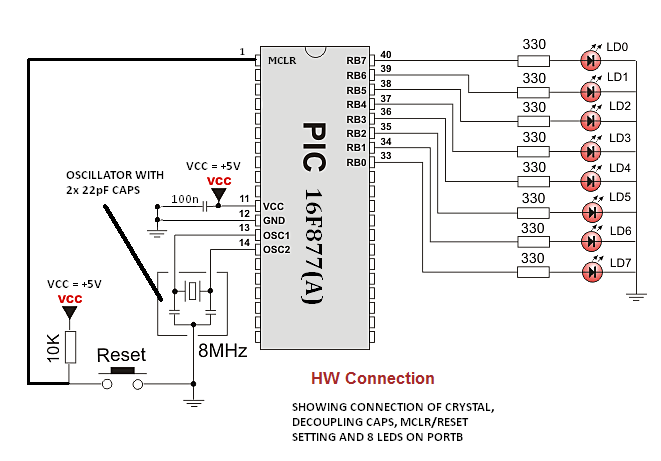
Firstly,I want to know how to connect the oscillator etc.
Secondly,I want to learn programming of PIC using C language.How do I go about it ?? What files to include,code etc.?? Please help.Please tell if there's any ebook or so.I intend to make a simple LED blinking program first !!Please help.
Thank You !
 

alrite..i give you an example file..try to figure out..that more helpful in future..
 

Attachments

  • MPLAB C++.zip
    134.7 KB · Views: 253
Hi,
This should be your basic hardware diagram:
70_1290615956.png


This is the link to the compiler I recommend - mikroC:
mikroC PRO for PIC - C compiler for PIC microcontroller - mikroElektronika

This is the link to a free ebook on using mikroC for programming PICs:
PIC Microcontrollers - Programming in C - Free Online Book - mikroElektronika

This is a sample program using the given hardware in mikroC:
Code:
void main(void){
   PORTB = 0; //Removes initial value that PIC holds in PORTB
   TRISB = 0; //This tells the PIC that PORTB should be output
   do{
      PORTB = 255; //255 = 11111111 in binary, so all LED's connected to PORTB glow
      delay_ms(500); //Wait for 500ms
      PORTB = 0; //Turn all LEDs off
      delay_ms(500); //Wait for 500ms
   }while(1); //Continuously do this
}

Go to the "Project" Menu. From the drop-down menu, select "Edit Project". Click "Default".

That book should get you going in using mikroC and PICs in no time.

Hope this helps.
Tahmid.
 
Hello,thanks to you all for help !!
I'll check the examples etc. an get back to you soon !
I am new to electronics too,doing Second Year Computer Engineering.
Once again thanks !
 

Hello,Thanks to You !! Because of You I successfully made my first LED Blinking program on PIC.
However,I have a small switch(the one which is to be connected on a PCB).It has 4 pins,and I am unaware how to use it as a reset button.So I haven't used it.Instead I've directly connected the MCLR pin to Vcc.So how to connect the switch ??

Also how to connect to ground ??
Once again thanks to You for making my first PIC project working !!
 
Last edited:

here we go...
this how u going to connect mclr
 

Attachments

  • mclr.jpg
    mclr.jpg
    138.2 KB · Views: 165
Hi,
Looking at this diagram:
**broken link removed**

I can tell, that you use either pins 1 and 3 or pins 2 and 4. Connect 1 pin to MCLR pin and the corresponding pin to gnd.

Hope this helps.
Tahmid.
 
here we go...
this how u going to connect mclr

But,on the protoboard two adjacent pins will get shorted,isn't it ??

---------- Post added at 22:03 ---------- Previous post was at 22:00 ----------

Hi,
Looking at this diagram:
**broken link removed**

I can tell, that you use either pins 1 and 3 or pins 2 and 4. Connect 1 pin to MCLR pin and the corresponding pin to gnd.

Hope this helps.
Tahmid.


Thanks,n how to ground on the protoboard??
 

But,on the protoboard two adjacent pins will get shorted,isn't it ??

---------- Post added at 22:03 ---------- Previous post was at 22:00 ----------


Thanks,n how to ground on the protoboard??

For that, you need to tell us which protoboard you use or give a circuit diagram.
 

For that, you need to tell us which protoboard you use or give a circuit diagram.
I have the general plastic protoboard . I don't know what it is called,but its a simple solderless breadboard.
 

I have the general plastic protoboard . I don't know what it is called,but its a simple solderless breadboard.

Okay, I thought you meant a dev board. In the protoboard, connect 1 pin to MCLR and the corresponding pin to ground. Ground would be the same point where the PIC ground is, pin 12 of the PIC.

Hope this helps.
Tahmid.
 

Okay, I thought you meant a dev board. In the protoboard, connect 1 pin to MCLR and the corresponding pin to ground. Ground would be the same point where the PIC ground is, pin 12 of the PIC.

Hope this helps.
Tahmid.

But,where has pin12 to be connected to make it ground??and what does the reset switch do??
Coz my circuit is working without reset switch .
 

ground mean negative...reset is use to restart your program cycle..
 

Can I also suggest some bedtime reading of introductory electronics -
Magazines books web pages - whatever you can gain access to.
Reading projects in magazines is often very helpful even if you don't
want to build the specific ones in that issue. You can pick up a lot
that way. Ideally something printed so you can relax while reading.

If you immerse yourself in this whilst doing your practical PIC work
things should become much clearer much faster.

jack
 

Hi,
Gnd means the 0v return line, or if you take it more simply the "negative" power supply (not really negative but 0v). Say, if you have a 5v power supply, the +5v or the "+" terminal is the positive power supply, here your VCC, the "-" terminal is ground.
Master clear is needed to reset the microcontroller. This means the microcontroller would stop doing whatever it was and start from the beginning as if you have just removed and then reconnected the power.

Hope this helps.
Tahmid.
 

Ya thanks !!
Actually seeing the diagram on the microe site got me confused over the -ve !!
But thanks a lot !!
 

Hello,
I am facing another problem !!
I use a 230V AC to 9V DC adapter for my circuit and there is a 5V voltage regulator in my circuit.
My circuit which was completely fine until it worked for 5-6 times,now it is not working ! The voltage convertor etc. is alright,I've already checked it.The same problem also appeared previously.I tried reprogramming the PIC once again,still it didn't work.Then reprogramming it 2-3 times worked.I feel that was just a coincidence,coz reading from the PIC showed the right program.I feel maybe there's some other problem which I am not getting !

Another thing is,now that the circuit is not working,while I switch off the Power Supply to the 9V adapter,there's a voltage at the output of the PIC making the LED blink,for a very short duration though.What may be the reason ??
Sorry so many questions !
 

Hey,what about simulators ?? Which can I use ?
and how do I go about learning to use motors etc. or the analog outputs with the PIC ??
Thanks.
 

Status
Not open for further replies.

Similar threads

Part and Inventory Search

Welcome to EDABoard.com

Sponsor

Back
Top