reef88
Junior Member level 2
hi,
can someone in this forum convert verilog code to vhdl code..please...
this is the code:
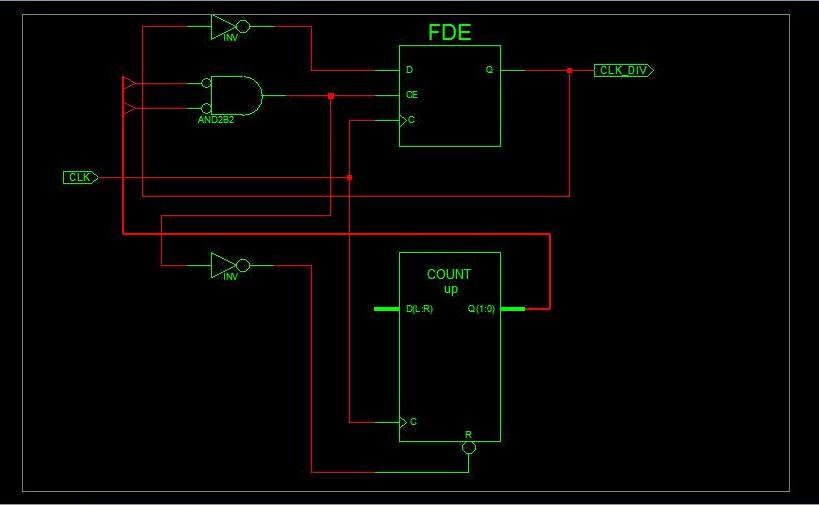
module CLK_DIV(
input CLK,
output reg CLK_DIV=0
);
reg [1:0] REGISTER=0;
always@(posedge CLK)
begin
REGISTER<=REGISTER+1;
if(REGISTER==4'b00) //creates a 0.04us 25MHz
begin
CLK_DIV <= ~CLK_DIV;
REGISTER<=0;
end
else
CLK_DIV <= CLK_DIV;
end
endmodule
can someone in this forum convert verilog code to vhdl code..please...
this is the code:
module CLK_DIV(
input CLK,
output reg CLK_DIV=0
);
reg [1:0] REGISTER=0;
always@(posedge CLK)
begin
REGISTER<=REGISTER+1;
if(REGISTER==4'b00) //creates a 0.04us 25MHz
begin
CLK_DIV <= ~CLK_DIV;
REGISTER<=0;
end
else
CLK_DIV <= CLK_DIV;
end
endmodule