Continue to Site

Welcome to EDAboard.com

Welcome to our site! EDAboard.com is an international Electronics Discussion Forum focused on EDA software, circuits, schematics, books, theory, papers, asic, pld, 8051, DSP, Network, RF, Analog Design, PCB, Service Manuals... and a whole lot more! To participate you need to register. Registration is free. Click here to register now.

180VDC motor control using 8051 ?

Status
Not open for further replies.

Rahul Ahuja

Newbie level 6
Joined
Nov 18, 2012
Messages
14
Helped
0
Reputation
0
Reaction score
0
Trophy points
1,281
Activity points
1,379
Hi
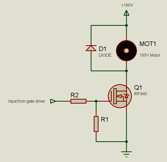
This is Rahul Ahuja. I want to control the speed of my 180V DC motor using 8051 microcontroller. Can any one suggest me that how to convert 5V DC output signals of controller into 180VDC signals for motor ??
 

mcu o/p will be onlu 0 or 5 volts. How do you control speed with 2 voltage levels?
 

You can use a mosfet to drive the motor.

For example you can use IRF840 if your current is below 2 amps

Select your mosfet as per your current needed.
 

For controlling the speed, use PWM.

The microcontroller will generate the PWM signal and the voltage will be 0V or 5V (depending on, if the output is high or low at that moment).

Use a MOSFET driver to drive a high voltage Power MOSFET which will drive the motor. Use a freewheel diode across the motor (it will be antiparallel to the motor).

One common (and quite cheap) high voltage Power MOSFET is the IRF840. It is rated at 500V, 8A. So, you can see if you can use it. By the way, what is the power rating of the motor?

Hope this helps.
Tahmid.
 
Hi Tahmid
Thank you so much for your support.
The motor rating is 180VDC, 2.2A, 0.5hp.

Actually i am little bit confused regarding IRF840. IRF840 has 3 legs, please tell me how will i do the connections to get 180VDC using 5VDC from controller.
 

Before going on to work with high voltage such as 180V, you should familiariaze yourself with Pulse Width Modulation and MOSFETs.

Read up on MOSFETs so that you know what they are and how they work.

The output of the 8051 will go to a MOSFET driver. You may use a driver chip such as TC427 or you may use a discrete driver made with transistors. The driver circuit will then drive the MOSFET gate. The MOSFET source will be connected to ground and the MOSFET drain to the -ve of the motor. The +ve of the motor goes to +180V. Connect a diode across the motor (its cathode to +180V and its anode to MOSFET drain).

Hope this helps.
Tahmid.
 
Thanks Tahmid

Surely i will first read the MOSFETs.
I have worked on PWM to control the DC motor of 12v.

Thanks
 

If you can upload, it will be very helpful for me.
 

Here is the connection diagram:
9665312700_1353240734.png


Now you need to decide which driver to use.
 
Thanks Tahmid

Can i use ULN2003 as a driver ?

Can you tell me the values required for R1, R2 and D1 ?
 

ULN2003 isn't really a MOSFET driver and you shouldn't use it as a MOSFET driver. Remember that it can only sink current but can not source it.

You can use TLP250, TC427, etc.
You may even be able to design a driver using transistors.

R1 could be 1k, R2 could be 10R and D1 could be MUR460.

Hope this helps.
Tahmid.
 
Thanks

Now let me study all this first then, i'll be more clear.
 

Yes. Go through them carefully. Make sure you read up on MOSFETs carefully. Make sure that you understand the MOSFET connections.

Feel free to ask any questions.
 

Yes, the circuit is fine. Remember that the TC426 is an inverting driver (as correctly shown in the diagram). So keep this in mind when programming and generating the drive signals. Increasing the duty cycle of the 8051 PWM will result in the MOSFET being driven with a decreased duty cycle, and vice versa.

Hope this helps.
Tahmid.
 

hi Tahmid i need a help to drive 180v dc motor speed controlling as shown in above circuit and as well as clockwise and anti clockwise rotation can you please tell me how it is possible
thank you
 

Status
Not open for further replies.

Part and Inventory Search

Welcome to EDABoard.com

Sponsor

Back
Top