Continue to Site

Welcome to EDAboard.com

Welcome to our site! EDAboard.com is an international Electronics Discussion Forum focused on EDA software, circuits, schematics, books, theory, papers, asic, pld, 8051, DSP, Network, RF, Analog Design, PCB, Service Manuals... and a whole lot more! To participate you need to register. Registration is free. Click here to register now.

[SOLVED] 16f676 simple example needed in hitech

Status
Not open for further replies.

fawadbutt

Member level 3
Joined
Oct 29, 2010
Messages
61
Helped
4
Reputation
8
Reaction score
4
Trophy points
1,288
Location
Lahore, Pakistan, Pakistan
Activity points
1,754
i m programming in 16f676 using hi tech 9.83 (pro)
i am writing the code it not working ,i jus on off led,

Code:
#include<pic.h>
#include<htc.h>
#define _XTAL_FREQ 4000000
__CONFIG(0x3f32);
//__CONFIG (0x3FB5);


void pic_init(void);

#define led0 RC0
#define led1 RC1
#define led2 RC2
#define led3 RC3
#define led4 RC4
#define led5 RC5

void main()
{
pic_init();
while(1)
{
led0=0;
led1=0;
__delay_ms(500);
led0=1;
led1=1;
}
}

void pic_init(void)
{
//TRISA=PORTA=0;//RB7-RB3 USE LCD 
//OSCCAL = 0b000000;
//ANSEL = 0b00000000;
TRISC=0;
PORTC=0;
//TRISA0=0xff;//USE ADC CHANNEL 1
}


here is my code its so simple but or working...plz
find the error or give me just a simple on/off led working example on protuse ,
Complier Hitech 9.83 (PRO),
Device pic16f676
Language C
 

You need a second delay, you are switching off the the leds, waiting 500ms the switching then on, then straight off again, you want a delay after switching them on.

Code:
void main()
{
pic_init();
while(1)
{
led0=0;
led1=0;
__delay_ms(500);
led0=1;
led1=1;
__delay_ms(500);
}
}
 

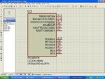
thanx for reply ,,,but yes one Delay is missing but this it not my problem,,,,,,,,when i load the file in proteus and Play no thing happen. i think problem is my fuse bit setting. aa.JPG
 

This means nothing to anyone?

__CONFIG(0x3f32);

You should use the defines that are in the include file, easier to see what is configured.

__CONFIG(INTIO & WDTDIS & PWRTEN & MCLREN & BOREN);
 

thanx ,,,my problem is solve ,,,the problem is MCLREN setting...:( my bad luck..

now I am trying use external interrupt and ADC ,,if you have any idea for this setting etc. plz share with me ,
its big help for me..
 

Are you attempting to configure External Interrupt (RA2) or Interrupt-On-Change (RA5::RA0)?

All three features are configured within the code through appropriate register settings.

Reference: PIC16F630/676 Datasheet, Section: 3.2.2 INTERRUPT-ON-CHANGE, Pg. 22

3.2.2 INTERRUPT-ON-CHANGE

Each of the PORTA pins is individually configurable as
an interrupt-on-change pin. Control bits IOCAx enable
or disable the interrupt function for each pin. Refer to
Register 3-4. The interrupt-on-change is disabled on a
Power-on Reset.

For enabled interrupt-on-change pins, the values are
compared with the old value latched on the last read of
PORTA. The ‘mismatch’ outputs of the last read are
OR’d together to set, the PORTA Change Interrupt flag
bit (RAIF) in the INTCON register.

This interrupt can wake the device from Sleep. The
user, in the Interrupt Service Routine, can clear the
interrupt in the following manner:

a) Any read or write of PORTA. This will end the
mismatch condition.

b) Clear the flag bit RAIF.

A mismatch condition will continue to set flag bit RAIF.
Reading PORTA will end the mismatch condition and
allow flag bit RAIF to be cleared.

Reference: PIC16F630/676 Datasheet, Section: 9.4.1 RA2/INT INTERRUPT, Pg. 67

9.4.1 RA2/INT INTERRUPT

External interrupt on RA2/INT pin is edge-triggered;
either rising if INTEDG bit (OPTION<6>) is set, or
falling, if INTEDG bit is clear. When a valid edge
appears on the RA2/INT pin, the INTF bit
(INTCON<1>) is set. This interrupt can be disabled by
clearing the INTE control bit (INTCON<4>). The INTF
bit must be cleared in software in the Interrupt Service
Routine before re-enabling this interrupt. The RA2/INT
interrupt can wake-up the processor from Sleep if the
INTE bit was set prior to going into Sleep. The status of
the GIE bit decides whether or not the processor
branches to the interrupt vector following wake-up. See
Section 9.7 “Power-Down Mode (Sleep)” for details
on Sleep and Figure 9-13 for timing of wake-up from
Sleep through RA2/INT interrupt.

Note:
The ANSEL (91h) and CMCON (19h)
registers must be initialized to configure an
analog channel as a digital input. Pins
configured as analog inputs will read ‘0’.
The ANSEL register is defined for the
PIC16F676.

Reference: PIC16F630/676 Datasheet, 7.0 ANALOG-TO-DIGITAL CONVERTER (A/D) MODULE (PIC16F676 ONLY), Pg. 45


Post your attempts in code so we can advise you further.


BigDog
 

Are you attempting to configure External Interrupt (RA2) or Interrupt-On-Change (RA5::RA0)?

All three features are configured within the code through appropriate register settings.

Reference: PIC16F630/676 Datasheet, Section: 3.2.2 INTERRUPT-ON-CHANGE, Pg. 22


Reference: PIC16F630/676 Datasheet, Section: 9.4.1 RA2/INT INTERRUPT, Pg. 67


Reference: PIC16F630/676 Datasheet, 7.0 ANALOG-TO-DIGITAL CONVERTER (A/D) MODULE (PIC16F676 ONLY), Pg. 45


Post your attempts in code so we can advise you further.


BigDog


hey
1-from the datasheet if we use analog input as a digital we must declare ANSEL 0x91,,,but if i write the 0x91 value in ANSEL my softwre is not working ,,but if i clear ANSEL register 0x00 its working ........?
2-what can i do when i use some pins as a digital and and some as a analog input.
 

Sorry for late Reply.....my trying to run lcd on 16f676....and i done it....but i am still facing the ADC Problem ...i dont know why ADC not working .. plz check my code ::
its my main coding
Code:
#include<htc.h>
#define _XTAL_FREQ 4000000
#include"my4lcd.h"
#include"adc.h
//#include"delay.h"
////////////////FUSE BIT SETTING/////////////////
__CONFIG(0x3ff4);		//16f676 Configration
//__CONFIG(INTIO & WDTDIS & PWRTEN & MCLREN & BOREN);
////////////////////FUNCTION's///////////////////
void pic16f676_init(void);
/////////////////////////////
#define on 0
#define off 1
#define LED	RA5
//////////////////////OUTPUT's////////////////////

/////////////////////Variable's////////////////////
//long int read;
//////////////////////MAIN///////////////////////////
void main()
{
unsigned int adc_result; 
pic16f676_init();
lcd_init();
while(1)
{
adc_result=adc_read(ch0);
lcd_text("ADC",_1st);
lcd_cmd(_2nd);
adc_display(adc_result);
//LED=~LED;
//__delay_ms(500);

}
}
///////////////////END MAIN//////////////////////////

//////////16F676 IC SETTING///////////////////////////
void pic16f676_init(void)
{
//INTCON =0b10001000;// ' Enable external interrupt <-bit 3 = 1 enable interrupt on change
//TRISA=PORTA=0;//RB7-RB3 USE LCD 
//OSCCAL = 0b000000;
ANSEL = 0b00001000;		// Select Channel 0 
//ANSEL =0x00;		// (ADC register)ADC off
CMCON =0x07;	// (Comparator Register) Comparator off
//TRISA=0b00000100;//0x04;
//PORTA=0b00000100;//0x04;
//TRISC=0x28;//0b00101000;
//TRISA=0xff;
//PORTA=0xff;
//PORTC=0xDF;
TRISC=0;
PORTC=0;
TRISA=0b00001000;
PORTA=0b00001000;
//TRISA0=0xff;//USE ADC CHANNEL 1
}

///////////////////////END/////////////////////////////
here is ADC Configration:
Code:
#ifndef adc_H
#define adc_H

#define ch0 0b01000001
#define ch1 0b01001001
#define ch2 0b01010001
#define ch3 0b01010001
#define ch4 0b01010001
#define ch5 0b01010001
#define ch6 0b01010001
#define ch7 0b00011101


unsigned char d1,d2,d3,d4;
long tlong;
void adc_init(int i);
int adc_read(long k);
unsigned int adc_res(void);	
int result=0;//,val;

int adc_read(long k)
{
adc_init(k);
result=0;
result=adc_res();
tlong = ADRESH;
tlong = tlong*256;
tlong+=result;
//tlong=(tlong/4);	///for 8 bit
return tlong;
}

int adc_display(long tlong)
{
d4 = tlong / 1000;
d3 = (tlong / 100)%10;
d2 = (tlong / 10)%10;
d1 = tlong %10;
d1+=48;
d2+=48;
d3+=48;
d4+=48;
lcd_data(d4);
lcd_data(d3);
lcd_data(d2);
lcd_data(d1);
}
int c_display(long tlong)
{
d4 = tlong / 1000;
d3 = (tlong / 100)%10;
d2 = (tlong / 10)%10;
d1 = tlong %10;
d1+=48;
d2+=48;
d3+=48;
d4+=48;
lcd_data(d3);
lcd_data('.');
lcd_data(d2);
lcd_data(d1);
}
void adc_init(int i)
{
__delay_us(20);
///msb--------lsb//
///D7---------D0//
//ADCON1=0b10000010;	//RJ,/000/,5/0
ADCON1=0b00000000;	//RJ,/000/,5/0
__delay_us(20);
///msb--------lsb//
///D7---------D0//
ADCON0=i;//	//FOSC/2,RA0/AN0,GO=0,/0/,EN=1; 
//
}

unsigned int adc_res(void)
{
ADRESL=0;
__delay_us(10);
GO=1;
while(GO)
{

continue;

}
return ADRESL;

}

#endif
 

Are you intrested in MikroC instead of Hitech?
MikroC have lot of libraries so that you can use them directly. eg. LCD,UART,I2C,SPI,KEYPAD etc

Led blinking code in mikroc (using PortA)

Code:
void main()
{
ANSEL=0x00; //making porta as digital
TRISA=0x00; //make Porta as Output.
while(1)
{
PORTB=0x00; //Switching off all leds connected to porta
Delay_ms(500); //500ms delay (library function)
PORTA=0xFF; //switching on all LEDs
Delay_ms(500);
}
}

No need to worry about fuse bits in MikroC create a project, then project settings change to HS oscillator required frq. LVP of, WDT off, MCLR desabled
 
Last edited by a moderator:

No need to worry about fuse bits in MikroC create a project, then project settings change to HS oscillator required frq. LVP of, WDT off, MCLR desabled

As someone who has seen and answered numerous questions pertaining to the MikroC and correctly setting the Configuration Register, I'm afraid that statement is pure rubbish.

And the Hi-Tech C Compiler and MPLAB IDE actually offer more flexibility to correctly set the Configuration Register, then the MikroC IDE/Compiler.


Led blinking code in mikroc (using PortA)

Code:
void main()
{
ANSEL=0x00; //making porta as digital
TRISA=0x00; //make Porta as Output.
while(1)
{
[COLOR="#FF0000"]PORTB[/COLOR]=0x00; //Switching off all leds connected to porta - [COLOR="#FF0000"]Should be PORTA[/COLOR]
Delay_ms(500); //500ms delay (library function)
PORTA=0xFF; //switching on all LEDs
Delay_ms(500);
}
}

I would also add the task of change the state of a PORT or an LED in Hi-Tech is no more complex then when using MikroC.

Especially if you code it correctly which your example is not.

Besides, the OP's post concerns the ADC module, not blinking an LED.


BigDog
 

Status
Not open for further replies.

Part and Inventory Search

Welcome to EDABoard.com

Sponsor

Back
Top