sahu
Advanced Member level 2
- Joined
- Oct 9, 2009
- Messages
- 516
- Helped
- 68
- Reputation
- 130
- Reaction score
- 62
- Trophy points
- 1,308
- Location
- Uttar pradesh (INDIA)
- Activity points
- 3,876
dear friend
i am new in pic project.
Pls help me .
[Reward on this project $100-$300. till 30-10-09 only. my mail id{shivendrakumarsahu77@yahoo.com}]
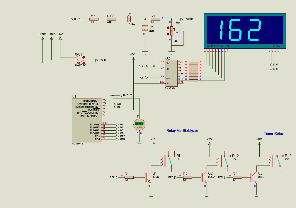
Only one L.T. is required. Please do wiring as per above diagram.
When you connect 95V input from variac the output should be 200V. Now increase input and check output.
When output reaches between 244-245V
preSet Setting and After Setting once relay
R3 goes ON and output will reach near about to 205V. Runcheck all steps.
Low cut shall be work on connecting Jumper J2
If time delay mode is presented the LED blinks sholly at the time of power on.
If voltage is out of range LED blinks fastly. On high voltage buzzer starts beeping slowly.
Sorry, but you need login in
i am new in pic project.
Pls help me .
[Reward on this project $100-$300. till 30-10-09 only. my mail id{shivendrakumarsahu77@yahoo.com}]
Only one L.T. is required. Please do wiring as per above diagram.
When you connect 95V input from variac the output should be 200V. Now increase input and check output.
When output reaches between 244-245V
preSet Setting and After Setting once relay
R3 goes ON and output will reach near about to 205V. Runcheck all steps.
Low cut shall be work on connecting Jumper J2
If time delay mode is presented the LED blinks sholly at the time of power on.
If voltage is out of range LED blinks fastly. On high voltage buzzer starts beeping slowly.
Sorry, but you need login in