Continue to Site

Welcome to EDAboard.com

Welcome to our site! EDAboard.com is an international Electronics Discussion Forum focused on EDA software, circuits, schematics, books, theory, papers, asic, pld, 8051, DSP, Network, RF, Analog Design, PCB, Service Manuals... and a whole lot more! To participate you need to register. Registration is free. Click here to register now.

16F676 BASED 90-290 VAC 5 STEP AUTOMATIC DIGITAL STABLIZER

Status
Not open for further replies.
Hi Tahmid,
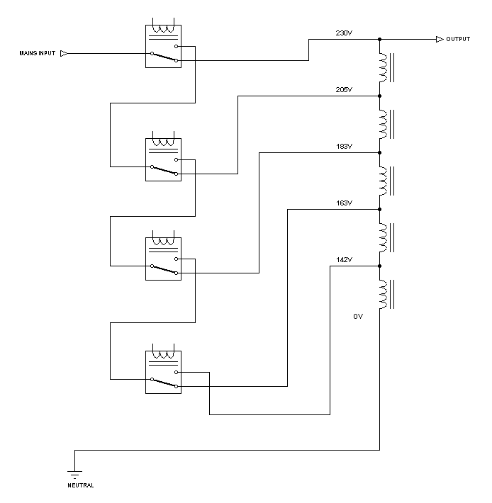
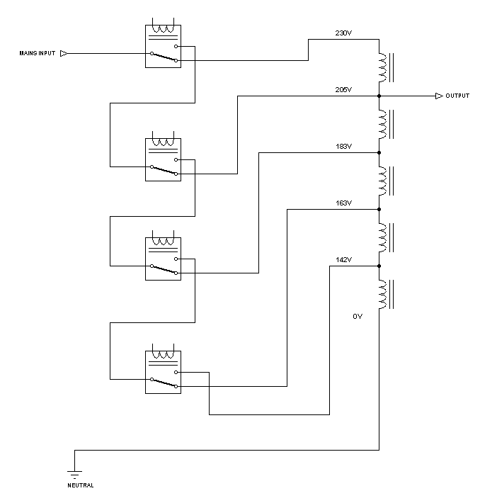
Just to be sure, what is the input range? and is the output 200/205 - 230/236 or 200/205 - 224/230 ?

I didn't redesigned it again using uC since the demand is rather low since many years.
I work lately on controllers for the industry (high power using bi-thyristors).
 
Last edited:

How about an input range of 140 to 250v? I was thinking about designing one with an ATMEGA8 with input and output voltage display. The output range could be about 200/205 to 224/230.

---------- Post added at 00:29 ---------- Previous post was at 00:23 ----------

There's a very high demand for voltage stabilizers here. Maybe I could give it a shot.
 

200/205 224/230
178/183 200/205
159/163 178/183
142/145 159/163

The numbers are rounded

How it is calculated:
200, 205 and 230 are given
224 = 230/205 * 200

K= 205/230

178 = K*200 , 183 = K*205
159 = K*K*200 , 163 = K*K*205
142 = K^3*200 , 145 = K^3*205
 
Last edited:
  • Like
Reactions: Tahmid

    Tahmid

    Points: 2
    Helpful Answer Positive Rating
When the transformer is designed, the higher value is considered.
Let us assume that the voltage is at 142V, the output will be 200V if the mains is connected to the lowest tap.
Slowly the mains goes up and becomes close to 163V, the output will be close to 230V.
At 163V, the controller selects the next (above) tap. so the output will return to 205V.
Now if the mains becomes a little bit below 163 ... close to 159V, the output will decrease from 205v to 200V without the need to change the tap selection.
This is called hysteresis (like it is used in schmitt trigger gates)
So assuming the mains keeps going up... the output will swing between 205V and 230V
And if the mains starts high and keeps going down... the ouput will swing between 200V and 224V.

Kerim
 
Last edited:
  • Like
Reactions: Tahmid

    Tahmid

    Points: 2
    Helpful Answer Positive Rating
Let us assume that the voltage is at 142V, the output will be 200V if the mains is connected to the lowest tap.
Slowly the mains goes up and becomes close to 163V, the output will be close to 230V.
At 163V, the controller selects the next (above) tap. so the output will return to 205V.
Now if the mains becomes a little bit below 163 ... close to 159V, the output will decrease from 205v to 200V without the need to change the tap selection.
To be continued...

how can calculate i\p & o\p voltage in stabilizers case ?
 

how can calculate i\p & o\p voltage in stabilizers case ?

We do it according to the consumer request (I mean the general demand of the local market).

Or please be more specific... your questions need to be given as it is done in any math or physics problem... godd given data... result a good solution :)
 

Is this diagram correct?


---------- Post added at 01:01 ---------- Previous post was at 00:59 ----------

When the transformer is designed, the higher value is considered.
Let us assume that the voltage is at 142V, the output will be 200V if the mains is connected to the lowest tap.
Slowly the mains goes up and becomes close to 163V, the output will be close to 230V.
At 163V, the controller selects the next (above) tap. so the output will return to 205V.
Now if the mains becomes a little bit below 163 ... close to 159V, the output will decrease from 205v to 200V without the need to change the tap selection.
This is called hysteresis (like it is used in schmitt trigger gates)
So assuming the mains keeps going up... the output will swing between 205V and 230V
And if the mains starts high and keeps going down... the ouput will swing between 200V and 224V.

Kerim

I think I get the control algorithm now. Thanks! Can you help with the transformer tapping voltage selection? I'm pretty confused with that.

---------- Post added at 01:03 ---------- Previous post was at 01:01 ----------

Is this correct?
 
Is this diagram correct?


---------- Post added at 01:01 ---------- Previous post was at 00:59 ----------


I think I get the control algorithm now. Thanks! Can you help with the transformer tapping voltage selection? I'm pretty confused with that.

---------- Post added at 01:03 ---------- Previous post was at 01:01 ----------

Is this correct?

both diagram correct are currect as per ur & consumer request (I mean the general demand of the local market).
 

Is this diagram correct?

The upper part is not needed... the 200V is the output

Added:
But as Sahu has suggested the upper relay will be needed as a step down... so with this the input can be higher than 230V
By the way, each tap must be designed for its highest input (not the lower ones)

Added:
To say if the connections are correct or not... depends on the way the uC will drive the relays... the relays has no numbers and we will assume their shown position is for the off state.
 
Last edited:
  • Like
Reactions: Tahmid

    Tahmid

    Points: 2
    Helpful Answer Positive Rating
We do it according to the consumer request (I mean the general demand of the local market).

Or please be more specific... your questions need to be given as it is done in any math or physics problem... godd given data... result a good solution :)

no sir my mean ...
when i\p 142V & o\p output will be 200V if the mains is connected to the lowest tap.
but when Slowly the mains goes up and becomes close to 163V, the output will be close to 230V. at lowest tap
 

So, using the 2nd circuit with an input voltage of 140 to 240V, and the control algorithm mentioned, it should work properly, right? I'm including the uper relay for step down. It's okay, right?

---------- Post added at 01:12 ---------- Previous post was at 01:09 ----------

no sir my mean ...
when i\p 142V & o\p output will be 200V if the mains is connected to the lowest tap.
but when Slowly the mains goes up and becomes close to 163V, the output will be close to 230V. at lowest tap

If I understood it right, when input = 162V (1v below when the next relay will be turned on), output voltage will be (at 200V tapping) = 200 - 142 + 162 = 220 at lowest tap.

That should be acceptable.
 

Perhaps there is a need to draw Vout versus Vinput (mains) while up (increasing) and while down (decreasing) ;)
 

So, I can use this:


With control voltages:
200/205 224/230
178/183 200/205
159/163 178/183
142/145 159/163

as has been shown

By the way,
How it is calculated:
200, 205 and 230 are given
224 = 230/205 * 200

K= 205/230

178 = K*200 , 183 = K*205
159 = K*K*200 , 163 = K*K*205
142 = K^3*200 , 145 = K^3*205

Great stuff!

So, is my setup right?

---------- Post added at 01:35 ---------- Previous post was at 01:25 ----------

To say if the connections are correct or not... depends on the way the uC will drive the relays... the relays has no numbers and we will assume their shown position is for the off state.

Yes, the shown position is when the relay is in normally connected mode. So, it is off. The microcontroller will drive them at the said voltages, as calculated, with hysteresis.
 

what both are say about this diagram .
it will work 95v to 420v i\p & o\p will between 200v to 240v ,means u can use 1 phase or 2 phases
95v _ to 420v.PNG
 

as has been shown

By the way,


Great stuff!

So, is my setup right?

i think it is for step up case .& what's the calculation of step down ?
K is constant value ?

---------- Post added at 01:18 ---------- Previous post was at 01:16 ----------

Is your rightmost relay to turn off the output?
yes RL5 for time delay & hi\low cutoff.
 

K is constant for a particular regulated output only ... in the example above it was 205/230 (or 200/224).
By changing the limits, K would change accordingly.

Added:
Just to be sure, if the input is 137V what will be the output?
 

K is constant for a particular regulated output only ... in the example above it was 205/230 (or 200/224).
By changing the limits, K would change accordingly.

Added:
Just to be sure, if the input is 137V what will be the output?
close to 240v
 

and to which voltage it can go up?

unless the above tap (200V) will be selected if it goes above 137V... in this case the output will be down to about 163V (240 *137/200)... unless I miss something to understand.
 
Last edited:

Status
Not open for further replies.

Part and Inventory Search

Welcome to EDABoard.com

Sponsor

Back
Top