Continue to Site

Welcome to EDAboard.com

Welcome to our site! EDAboard.com is an international Electronics Discussion Forum focused on EDA software, circuits, schematics, books, theory, papers, asic, pld, 8051, DSP, Network, RF, Analog Design, PCB, Service Manuals... and a whole lot more! To participate you need to register. Registration is free. Click here to register now.

Funny MonteCarlo Phase response when doing Middlebrook

Status
Not open for further replies.

jgk2004

Full Member level 5
Joined
Dec 1, 2009
Messages
274
Helped
77
Reputation
154
Reaction score
74
Trophy points
1,308
Location
Munich Germany
Activity points
3,520
Hello All,

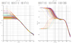
I am seeing something very interesting when doing a monte carlo of 300 for my designed amplifiers open loop response.

Can anyone explain why my phase is split and mirrored around 90degrees then meets up with the other runs?

My PM looks great and Gaussian around 70degrees so I would say everything is good, but do I have to worry about this weird starting of the phase?

Thanks

Johnk
 

Attachments

  • amp1monteplot_1371.png
    amp1monteplot_1371.png
    84.5 KB · Views: 157

jgk2004 said:
................
My PM looks great and Gaussian around 70degrees so I would say everything is good, but do I have to worry about this weird starting of the phase?
........

Yes, I am afraid you have to worry.
All phase responses starting at 0 deg. indicate instability.
You cannot solely trust ac analyses, because they sometimes indicate stability for unstable systems. And in this context, a rising phase characteristic looks dangerous.
Try some analyses in the time domain to reveal stability problems.
Regards LvW
 

Hi LvW,

So I totally agree with you about the AC response can not be trusted completely and a trans sweep is needed. But I am designing this amplifier to be used as an integrator... How do I do the trans sweep? If I connect it up as inverting and do a trans with a step everything looks fine, see attached. But the amplifier will not really be used like this... What would you recommend?


John

Added after 1 minutes:

Also LvW,

Do you have any comments on my other post?

Opamp Loading question Testbench AC response


Thanks for the help
John
 

jgk2004 said:
..........
But I am designing this amplifier to be used as an integrator... How do I do the trans sweep? If I connect it up as inverting and do a trans with a step everything looks fine, see attached. But the amplifier will not really be used like this...
............
............
Do you have any comments on my other post?

Hi John,

I don´t understand your problem: Why do you connect the circuit as an integrator, although it "will not really be used like this" ??

But anyway - I cannot comment if it looks "fine" or not. What do you expect at the output? Does the result correspond with theory?
I can only share my opinion if I see the circuit and the input signal.

And - what do you mean with "other post"?

Regards LvW
 

Hi LvW,

Sorry for the confusion. I am designing this amplifier to be used as an integrator in a system.. I am finding that when designing these amplifiers they need to be simulated for stability as they will be used. If my testbench is just a opamp connected as a buffer, and I check its stability it is not the same as if it was connected as an integrator..hense the middlebrook method.. That is why I am having trouble thinking of how to simulate its transient response in some other configuration, hense the inverting opamp configuration response i posted before would then not truly represent the integrators tran response....

I did just do a tran response with the amplifier connected as it will be used an integrator..The response looks fine to me any comment? Also is this the correct way to do this?


The other post I am talking about is this one


Thanks

John
 

Hi John,

I just have sent you a PM.
 

Hi,
To me it looks like amp is falling over on corners. When you run corners do you see similar phase behaviour?
Can you run monte carlo mismatch only?
 

Sorry this took me so long to get back. With process everything looks great. When simulating Mismatch only, it shows it is all due to mismatch. One question is when MonteCarlo says this is your mismatch is this worst case IE, you don't know how to layout, nothing is symmetrical. Or are these mismatch simulations set for a good layouter?


What I am guessing is these are worst case never seen in real silicon if your layouter knows what he/she is doing!

What do you guys think???????
 

jgk2004 said:
One question is when MonteCarlo says this is your mismatch, is this worst case, IE, you don't know how to layout, nothing is symmetrical. Or are these mismatch simulations set for a good layouter?
...
What do you guys think???????
AFAIK the MC mismatch parameters are given for totally perfect layout (centroid + dummies), i.e. they should reflect only Pelgrom mismatch (for mismatch_only), which means (W*L) dependent mismatch.
 

Hello John,
Did you also check out the numerical data on the plots? Are you sure its not a plotting problem?
The mismatch data added to model files is from test patterns in the process wafers, these test patterns usually measure the parameters of 2 devices placed side by side. They have these test patters for different sized devices and then they get the matching coefficient using the best fit line according to the 1/sqrt(wl) scaling.
 

Status
Not open for further replies.

Part and Inventory Search

Welcome to EDABoard.com

Sponsor

Back
Top