Continue to Site

Welcome to EDAboard.com

Welcome to our site! EDAboard.com is an international Electronics Discussion Forum focused on EDA software, circuits, schematics, books, theory, papers, asic, pld, 8051, DSP, Network, RF, Analog Design, PCB, Service Manuals... and a whole lot more! To participate you need to register. Registration is free. Click here to register now.

1602 Display Problem

Status
Not open for further replies.

radiotec

Newbie
Joined
Nov 8, 2019
Messages
4
Helped
0
Reputation
0
Reaction score
0
Trophy points
1
Activity points
26
1602 Display Problem

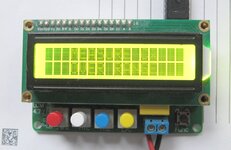
I just turned on my LC-100 LC meter and now the display is really weird looking.

If I turn the display at a certain angle I can just about read what it normally displays and it looks like its working..
Not sure what to do, I was thinking about disabling the back light but I really do not think it would help.

Any idea what these characters are that are being displayed and how to get rid of them ?

Any help would be appreciated.
 

Attachments

  • sssssssssssssssss.jpg
    sssssssssssssssss.jpg
    468.8 KB · Views: 148

Yes the contrast bias is off, has shifted. Usually there is a miniature pot to adjust it,
or a R divider to set it. If one R on the divider is badly soldered or poor connection
that can also create this problem.

Note the contrast pin on your display is labeled VO, third pin from left in your pic.

The manufacture may have put the pot / R divider underneath the display. Usually
pot is 5K to 10K, so worst comes to worst you could "over power" it by attaching a 1K
pot to VO to get bias right. Thats assuming pot has not shorted in failure. You might
measure VO to ground to see whats its R looks like.


Regards, Dana.
 
Last edited:

Pin 2 VDD was 5V and pin3 VO was .117V
Also I just noticed that there is no trace coming off of pin3.
Looks like a throw away board. I think that I may just have to replace the display.
 

Attachments

  • 3333333.jpg
    3333333.jpg
    1.6 MB · Views: 155

Pin 3 trace is probably on the other side of the PCB. It has to be there for it to function.
It would be unusual for the pin to be left floating on the LC meter, normally it would connect to a variable voltage source as danadakk stated but that could be a potentiometer or a voltage from a DAC on the MCU. If the menu has a setting to adjust the contrast, that is where the problem lies but of course that could create the problem of not being able to see the menu in the first place.

Brian.
 

There is no trace visible on either side of the PCB indicating that its probably a multi-layer board. VO pin3 goes to R1 but has a a very high resistance on each side of the resister about 8 and 10K. R1 measures good 2.2K. Kind of think that there might be errors on the schematic. New 1602 from Amazon is arriving tomorrow. Will let you know the outcome.
 

Good news ! I insllalled the new 1602 display that I got from Amazone and it now works great.

Thanks everyone, I appreciate your help.
 

Status
Not open for further replies.

Part and Inventory Search

Welcome to EDABoard.com

Sponsor

Back
Top