amjadali56
Full Member level 3
Follow along with the video below to see how to install our site as a web app on your home screen.
Note: This feature may not be available in some browsers.
What you suggest,which value of resistance is ok,instead of 10k.I'm still wondering how fast you can turn off the mosfets with the 10k pull down.
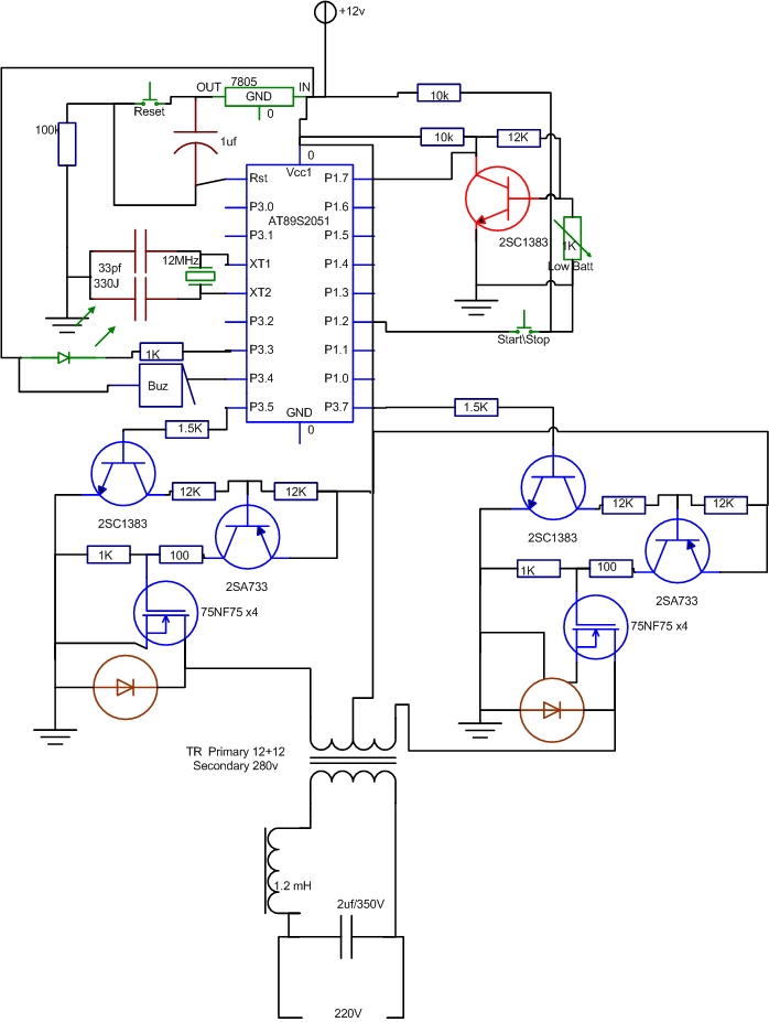
there is some confusing or either mistake in diagram that is atmel ic 89s2051 operting max at 5v.but it's vcc is connected directly with 12v.
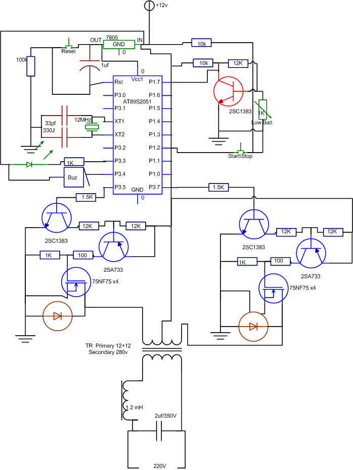
Thanx for pointing. it is serious mistake.
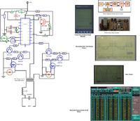
i am giving you the schema of the 12v to 220v 1500W swith mode Inverter Full Schematics & Pcb U can use this to set up
Output wave is Modified Sin.
thanx to all for such a great support and interest. i have completed my prj with your help and support.
how many amp trafo will i need to run this at 500w ?
