Continue to Site

Welcome to EDAboard.com

Welcome to our site! EDAboard.com is an international Electronics Discussion Forum focused on EDA software, circuits, schematics, books, theory, papers, asic, pld, 8051, DSP, Network, RF, Analog Design, PCB, Service Manuals... and a whole lot more! To participate you need to register. Registration is free. Click here to register now.

1500W Inverter Full Schematics And Pcb

Status
Not open for further replies.
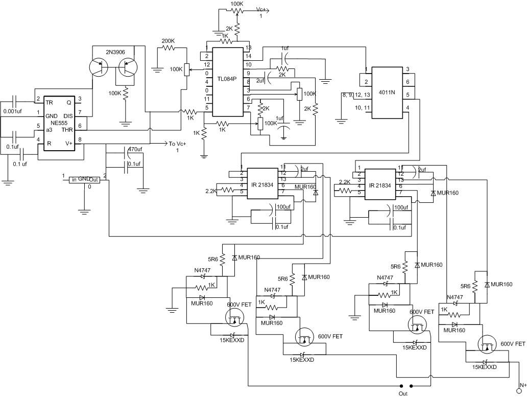
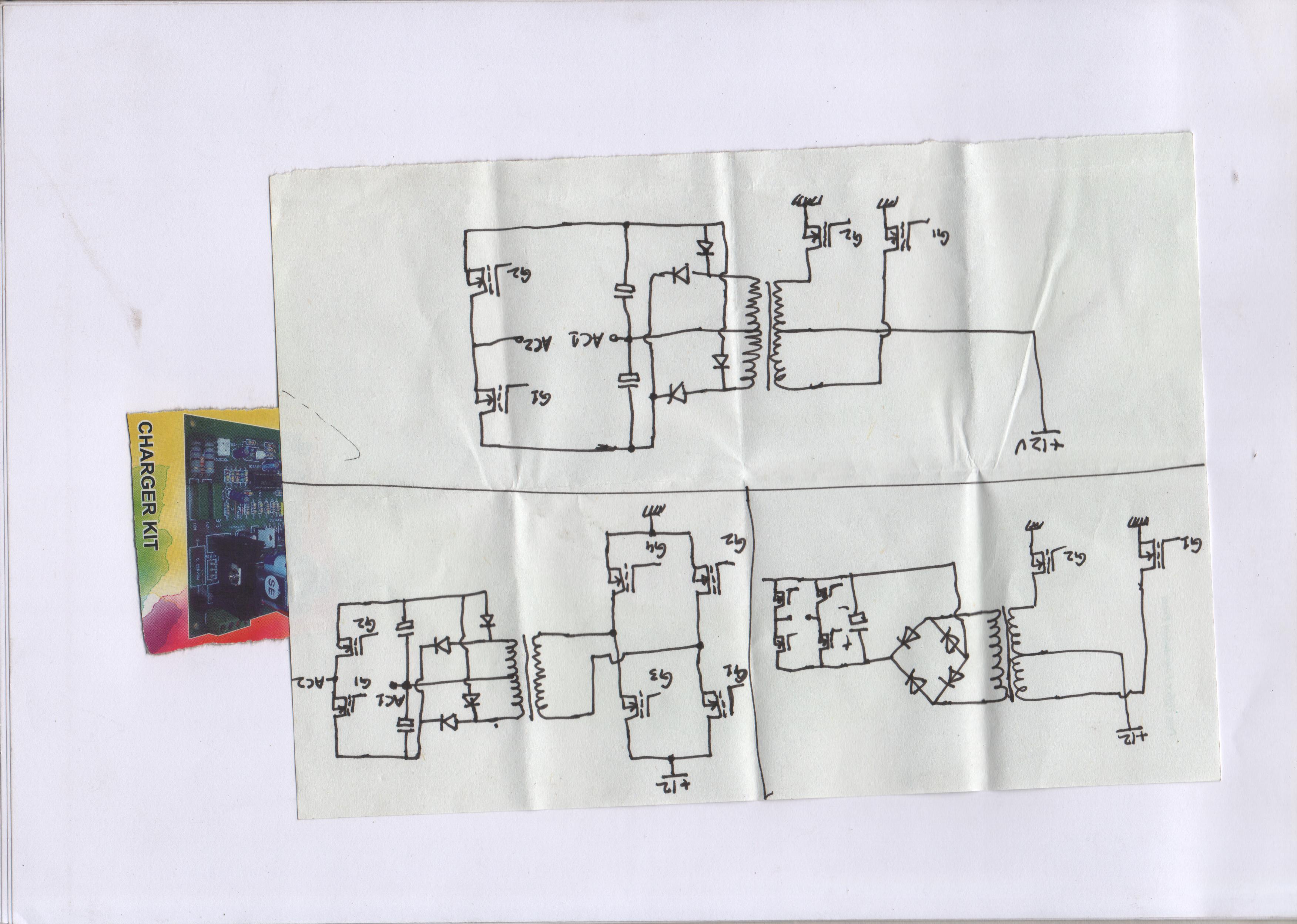
edaboard 1500w inverter schematic

cae20452

Hello.

Were are U

Plz Answer Questions.

Added after 9 minutes:

Here is a full inverter
 
Re: schema inverter 12v

Audioguru said:
Most simple inverters have a square-wave output. A modified sine-wave is just a square-wave with a step in it so its peak voltage is almost the same as a sine-wave.

A sine-wave inverter is much more complicated because it uses pulse-width-modulation at a high frequency to make a waveform with many steps in it then a simple LC filter smooths it into a sine-wave. Class-D audio amplifiers have a similar circuit.
The output Mosfets switch completely on and off to avoid wasting power.
Audioguru, why don't you come up with a good design for a sine wave inverter that is not limited to 1500 watt of power output? according to your posts you seem to know every thing about the topic.
PS my old bulky 4KW with a PIC and home made R2R network as sine wave generator and the huge 12 to 220 transformer is working for 5 years nonstop. zero maintenance except for one battery replacement.
 

Re: schema inverter 12v

chrismicro said:
Audioguru, why don't you come up with a good design for a sine wave inverter that is not limited to 1500 watt of power output? according to your posts you seem to know every thing about the topic.
Why should I design an inverter?
I have never needed an inverter because my electricity is reliable and I never go away to non-civilization to camp, fish, hunt or search for gold.
A modern Chinese sine-wave inverter is available everywhere for a low cost.
Many new cars come with a modern inverter.
 

Re: schema inverter 12v

Audioguru said:
chrismicro said:
Audioguru, why don't you come up with a good design for a sine wave inverter that is not limited to 1500 watt of power output? according to your posts you seem to know every thing about the topic.
Why should I design an inverter?
I have never needed an inverter because my electricity is reliable and I never go away to non-civilization to camp, fish, hunt or search for gold.
A modern Chinese sine-wave inverter is available everywhere for a low cost.
Many new cars come with a modern inverter.
I'm not talking about an inverter to drive my electric shaver when I'm camping, there is a need world wide for high power inverters and that is what this thread is about. Come on and take the challenge, show us what you can do.
 

Wow this circuit look great. But pcb you send is not of our work . if you realy wana help then u should send orignal pcb like which you made in PCAD of proteous of any other software
 

khawarsiddiq said:
Wow this circuit look great. But pcb you send is not of our work . if you realy wana help then u should send orignal pcb like which you made in PCAD of proteous of any other software
Me too, help me origin pcb file original ( protel or orcad ).
Thank you !
 

    V

    Points: 2
    Helpful Answer Positive Rating
iam trying to made a 500w 12vdc/230vac pure sine wave inverter using pulse width modulation, i want the circuit diagram ,pcb layout and detailed discription about this please anybody help me
 

Re: inverter schematics

capacitor,s(c54,c55)value show it is inverter from 12v dc to 110 volts ac.And Irf250 can not switch 220v DC(.for switching 220dc,transistor IRF460 is suitable).
If secondary of transformer is 110volts(ac) after bridge rectifire dc volt should be,160(without load)
 
audioguru! need a block diagram of transformer less inverter.
 

    V

    Points: 2
    Helpful Answer Positive Rating

    Akinabigail

    Points: 2
    Helpful Answer Positive Rating
audioguru! need a block diagram of transformer less inverter.
You do not make sense. I think you mean "transformer-less" (which does not use a transformer).
A transformer is used in an inverter to stepup the AC voltage. I have never seen an inverter that does not use a transformer.
Old inverters used a 50Hz or 60Hz transformer that was huge, heavy and expensive.
Modern inverters use a circuit that produces a high frequency then its transformer is small, light-weight and inexpensive.
 

Almost 18 batteries of 12 volts required for transformer less inverter.all batteries should conect in series.almost 216v dc.one can invert dc 216 volts into ac with h-bridge inverter circuit.
Power inverter used in car,boats etc,designed with 12 volt battery.
12v dc inverter circuit generate 220vac on secondery winding of transformer.these 220vac convert in dc volts with fast recovery diodes and capacitors.
Now dc volts are approximately 270vdc.one can see h-bridge inverter circuit here.it consist of 4 igbt or fets.
 

You do not make sense. I think you mean "transformer-less" (which does not use a transformer).
A transformer is used in an inverter to stepup the AC voltage. I have never seen an inverter that does not use a transformer.
Old inverters used a 50Hz or 60Hz transformer that was huge, heavy and expensive.
Modern inverters use a circuit that produces a high frequency then its transformer is small, light-weight and inexpensive.

i mean high frequency light weight transformer inverter,

---------- Post added at 10:12 ---------- Previous post was at 10:09 ----------

You do not make sense. I think you mean "transformer-less" (which does not use a transformer).
A transformer is used in an inverter to stepup the AC voltage. I have never seen an inverter that does not use a transformer.
Old inverters used a 50Hz or 60Hz transformer that was huge, heavy and expensive.
Modern inverters use a circuit that produces a high frequency then its transformer is small, light-weight and inexpensive.

i mean high frequency light weight transformer inverter, :-D
 

Hello Amjad,
Do you know how to make a high frequency powerful transformer?
Can you buy its ferrite core in your country?
What wave-form shape do you want at the output of your inverter? Sine-wave, modified sine-wave or square-wave?

You should attempt to make your own block diagram. There are two ways to make the circuit:
1) Make the modulated PWM signal at the battery voltage then step up its voltage with the transformer.
2) Use a simple high frequency power oscillator then use the transformer to stepup its voltage. Then rectify and filter the AC to make a high DC voltage. The DC voltage powers a high voltage modulated PWM circuit.
 
If ferrite core is not avail in market one can change old winding of computer,s power supply transformer(high frequency ferrite core).
A light weight inverter almost consist of DC to Dc converter.i mean 12 or 24 volt dc input and 250 dc out put.
out put 250v dc can be invert in 220 v ac with pulse width modulation(pwm) oscillator circuit.
in both sides pwm chip TL494 or SG3525(frequently use in computer power supply) can be use.
In 12 or 24v side IRF1404 and at 250 v dc IRF460,IRF840 .
IRF1404 can draw high current and need heat sink.
 
  • Like
Reactions: amjadali56

    amjadali56

    Points: 2
    Helpful Answer Positive Rating
    V

    Points: 2
    Helpful Answer Positive Rating
DC to Dc converter.... output 250v dc can be invert in 220 v ac with pulse width modulation(pwm) oscillator circuit.
No.
The peak voltage of a 220v AC sine-wave is 311V so the output of the DC to DC converter must be a little more than 311V.
The output Mosfets must also have this higher voltage rating.
 
got the idea: so helpful thanks Guru, thanks panjbtr
 

any helpful citation needed! (still working on this not completely finished)

 
  • Like
Reactions: mmika

    mmika

    Points: 2
    Helpful Answer Positive Rating
TRY TO ADD NUMBER ON ALL 4 FETS,LIKE Q1,Q2,Q3,Q4 OR FET1,FET2.....
THIS IS SECOND STAGE OF YOUR DESIRED POWER INVERTER.
AND CALLED H-BRIDGE OSCILLATOR CIRCUIT.
THIS CIRCUIT CONSIST OF TWO SETS OF 4 FETS.
EACH FET IN BOTH SETS IS CONECTED IN SERIES,DRIAN CONECTED WITH SOURCE(OUT 1 AND OUT2).
FOR 1000 WATT WE NEED 4 FETS IRF460.
AND AT 12 V SIDE WE CAN USE 8 FETS IRF 1404.
HIGH FREQUENCY TRANSFORMER(USED IN COMPUTER POWER SUPPLY),
ONLY CAN PROVIDE 250 WATTS MAX.
IT MEANS YOU HAVE TO USE 4 TRANSFORMERS OR YOU CAN USE HIGH FREQUENCY TRANSFORER(FERRITE CORE) OF 21 INCH MONITOR ,I THINK THIS CAN PROVIDE MORE WATTAGE THAN PC POWER SUPPLY.


Last edited by a moderator:

Status
Not open for further replies.

Similar threads

Part and Inventory Search

Welcome to EDABoard.com

Sponsor

Back
Top