Continue to Site

Welcome to EDAboard.com

Welcome to our site! EDAboard.com is an international Electronics Discussion Forum focused on EDA software, circuits, schematics, books, theory, papers, asic, pld, 8051, DSP, Network, RF, Analog Design, PCB, Service Manuals... and a whole lot more! To participate you need to register. Registration is free. Click here to register now.

Power rating of CFL bulb

Status
Not open for further replies.

eem2am

Banned
Joined
Jun 22, 2008
Messages
1,179
Helped
37
Reputation
74
Reaction score
24
Trophy points
1,318
Activity points
0
cfl bulb ratings

Hello,

I have a 15W CFL and looked at the current entering this bulb from the mains (i used a 12W resistor in series with the 'hot' line and looked across it with the scope)

Mains is 240V , 50Hz

The current came out as 59mA RMS, giving an input power of 14.2W.

I would have expected, with inefficiency, for the power input to be more like 18 Watts.

Do you think they have over-rated this bulb's power rating ?

..here is the bulbs input current....


2safb6d.jpg
 

cfl power rating

You need a very low resistor value and a true RMS voltage meter to measure the current.
The current times the voltage is the apparent power, not the actual power. The power factor determines how much the apparent power differs from the true power due to phase shift. Your resistor reduced the current.

I think a 14W bulb draws 14W of true power which might be 20W of apparent power that you and your electricity consumption meter cannot measure.
The bulb probably wastes about 2W in heat.

The current is higher when the bulb is cold and gradually decreases as it warms up.
 

cfl waveform

Apart from what has been said regarding true and apparent power, the measurement may be inaccurate.

I tested some electronic CFL, and found a real power input of +/- 5% around the nominal value. The power factor varied
between 0.5 for a cheap no-name DIY market product and 0.71 for a major manufacturers product. See respective
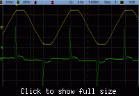
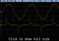
waveforms below. The oscilloscope current measurement isn't exact, cause I used a high current rogowski probe with 10
turns of the sensed conductor. I measured the input current, real power and power factor with a separate power meter.

230 V RMS 91 mA RMS 10.5 W 0.5 PF (no-name 11 Watt)
230 V RMS 89 mA RMS 14.7 W 0.71 PF (Osram 15 Watt)


cfl bulbs power factor

Thankyou FvM,

your waveforms are in fact very interesting, especially in light of the fact that the manufacturers are stating that the above waveforms have power factors of 0.5 and 0.71.

This is in fact a very interesting post now, as we see how manufacturers make false claims about power factor........

Do you know if these figures are the distortion factor , or the displacement factor, or the product of these two ?

At a guess, i would say that these figures are the displacement factor. This is not really the proper power factor but manufacturers regularly state displacement factor as the actual power factor.

Looking at your CFL waveforms, they are (like mine) nothing like sinusoidal, and i would estimate that the proper power factor (product of displacement factor and distortion factor) is very low indeed...probably about 0.1
 

cfl power ratings

The measurements represent the true power factor P/S, where S = Irms*Vrms. I'm not sure, if it's numerically a product
of displacement and distortion power factor (if they would be calculated individually), but at least it's smaller
than each of both. Modern electronic instruments are always considering all apparent power components respectively
displaying true P/S. An individual measurement of displacement or reactive power factor is more a historical topic.

Generally, I'm not aware of manufacturers makings false claims about power factor, although the properties of these
devices may be regarded disappointing.
 

measure current in a cfl

Compact fluorescent bulbs are low power and are used in homes.
The Watt-meters used in homes measure do not measure the apparent power which the poor power factor boosts. The meter measures only the real power.
So the electrical utility pays for the higher apparent power, not the home owner.
 

cfl ratings

Yes, exactly. Strictly spoken, the cost of apparent power is in the resistive losses in cables, overland lines and transformer
windings and in the extra current capacity that has to be provided. For this reason, industrial power consumers are charged
for apparent power use respectively have to keep strict limitations.
 

power factor of cfl bulb

hello,

i appreciate these posts....but i do say that looking at these current waveforms, and there shape which is miles from sinusoidal, that the power factor must be much less than 0.5

....only the fundamental delivers real power and the fundamental would only be a small part of that waveform....-that current waveform must be full of harmonics to make it so non sinusoidal.

i beg you to reconsider if the power factor really is 0.5.

it wouldnt surprise me if a modern instrument just measured the displacement factor (of the fundamental) and called that the power factor
.
 

user pays apparent power

They don't measure displacement factor. They measure Irms, Vrms and real power. You have e. g. P=15, S=30. That's,
how you get a 0.5 power factor.

You are able to verify the values from my DSO measurement printouts, BTW.
 

I understand this factor of poor pf of CFL. But how this problem can be solved? I mean how we can improve the pf also the performance of the CFL? Any idea?
 

As previously discussed in this (and other) threads, the low power factor of 0.5 to 0.7 is unwanted but not an actual problem for domestic lighting. To get rid of it, the CFL power supply has to implement a PFC inverter as it's basically required for large electronic power supplies e.g. for computers. It's not feasible with an acceptable effort these days.
 

But the pf of these CFL can be improved I think some extra energy consumption can be protected. In this way, how can we improve the pf of CFL?
 

In North America and maybe also in Europe, homes are not charged for a poor power factor. Only industry is charged.
 

as discussed, this is non-harmonic power factor. as parsevals theorem shows, the product of V*I in time is the same as V*I in frequency. the sudden current draws of the CFL bulb indicate a very high frequency component that is not present in the voltage waveform. Thus the measureable power factor is low. (very little of the RMS voltage and RMS current contributes to power in the frequency domain.) at the same time, very little is actual power.

---------- Post added at 07:05 ---------- Previous post was at 05:10 ----------

(also, in the US homes are charged for a low PF. but 10% of pure crap is still just 10%. The power companies seem to view this as better than the 100% power needed in cooking and other tasks.)

if you manage to get enough CFL lights that you manage to pull your overall, after AC/heating/cooking/cleaning/computing/enterataining/etc... power factor below some limit, you will get charged.
 

also, in the US homes are charged for a low PF
Hard to believe. How is this supposed to work? I know, that US homes have old fashioned eletromechanical meters, as used in most parts of the world. Is the power utility company doing interviews about amount of CFL and non-PFC electronics?

But the pf of these CFL can be improved I think some extra energy consumption can be protected. In this way, how can we improve the pf of CFL?
I fear, you didn't yet correctly understand what PF is. Review the respective discussion at edaboard.
 

Residential homes are not charged for poor power factor in U.S.

The circuit for a cheap CFL is full wave rectified AC with filter cap. The high voltage D.C. is chopped at 25 kHz to 40 kHz with a push-pull MOSFET output. This squarewave is put through a high frequency ballast inductor to bulb.

The filter cap short recharge period on the input sinewave peaks causes the current spikes and the poor power factor. There is some RF filtering on AC input to reduce the harmonic interference on power lines but it does little to improve power factor. This is no different then most older computer power supplies that do not have power factor correction frontends. The more ripple allowed on rectifier filter cap the lower and longer the input current spike and better the power factor. The power supplies are generally equivalent to around a P.F. of 0.6

The power factor correction frontend is usually a boost switcher after the AC rectifier that pulses the boosted DC proportional to AC sinewave input. This causes the filter cap charging to be spread with a sinusoidally shaped current profile across most of the AC input period yielding a good power factor.

As to question about input true power being less then bulb wattage rating, a fluorescent bulb light output is more efficient when excited with 25 kHz to 40 kHz comparied to 60 Hz inductive ballast drive. This allows the bulb to driven at lower power for same lumens output.

**broken link removed**
 
Last edited:

Status
Not open for further replies.

Similar threads

Part and Inventory Search

Welcome to EDABoard.com

Sponsor

Back
Top