delwin
Newbie level 6
I have a strange experience last night.
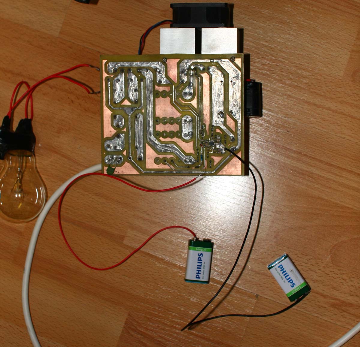
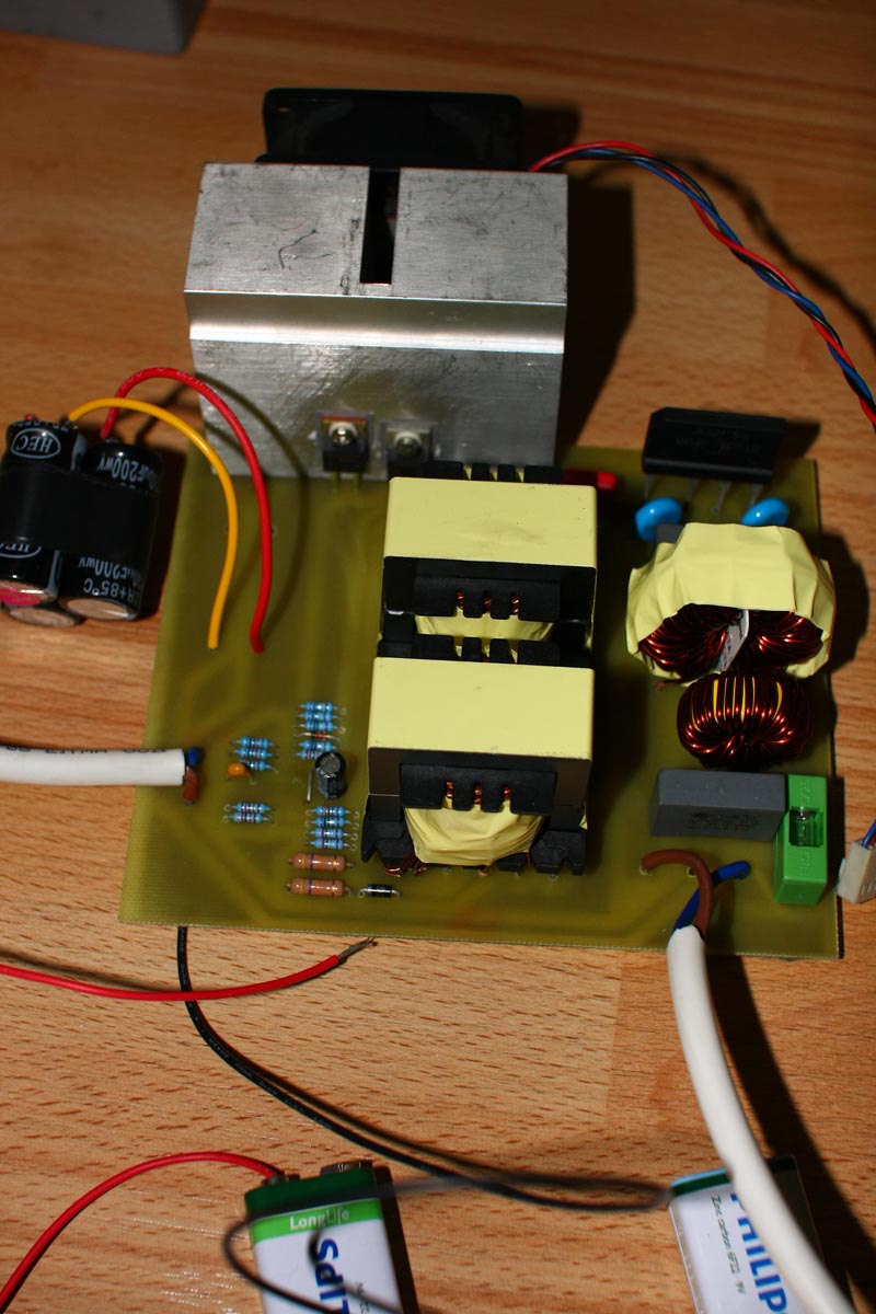
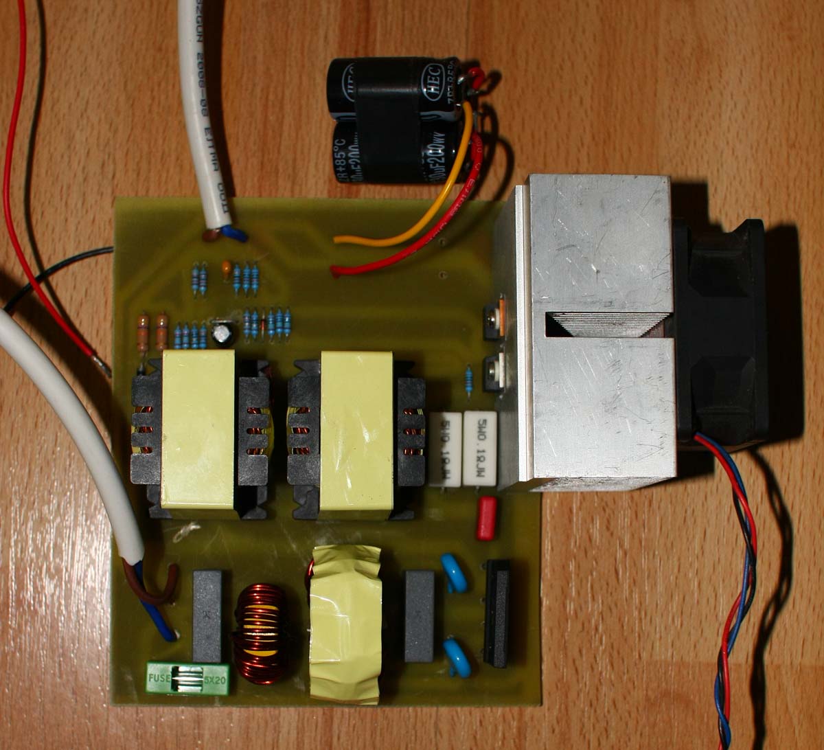
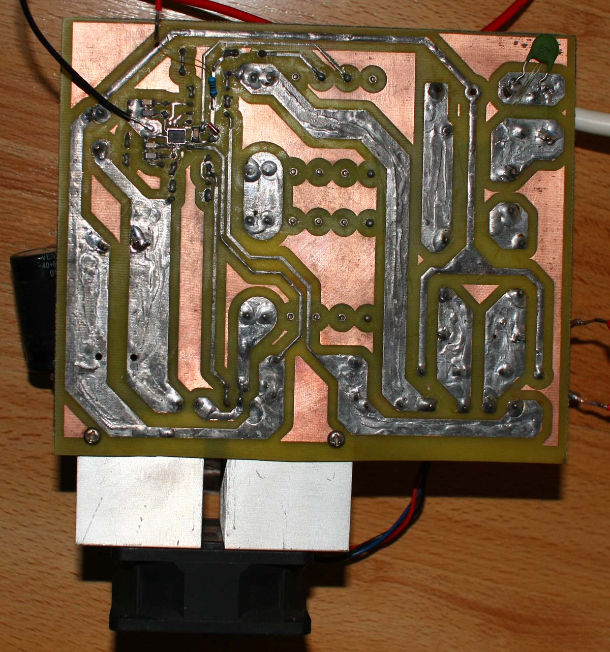
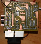
I'm building a PFC stage. 230VAC/50Hz input, 390-400VDC output.
I'm using the NCP1654 pfc controller, and everything is by the reference design. I use the XLS file to calculate the needed values for the Rs and Cs.
I triple check it and still I'm getting one and the same strange behavior.
I have connected in series two 75W/230V tungsteen wire bulbs as load.
I'm using a DT-838 and DT-830B digital multimeters.
There is 1A fuse, the power switch is a N-MOS SPP20N60S5 (600V/20A/Rdson=0,21R), the diode is 15A/600V UltraFast.
Multimeter is connected across the + and - outputs of the PFC,and is switched to 1000VDC range.
After powering the damn thing, the bulbs get normally bright, as every one of it is connected to a regular 230VAC. Nothing blows, no smoke, but...
the multimeter says 1300VDC!!!!
I have tested it with the two multimeters, the same result.
What do you thing of this?
I'm puzzled, as if there were really 1300VDC the N-MOS and DIODE and the BULBs would be a history already.
Is the problem with the metering tools, or there really could be a 1300VDC?
The PFC is calculated for 1200W load nominal, but I'm testing it at about 75W just to see whether it works or not.
Some comments?
Thank you
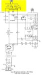
The scheme the device is build around could be find at the end of the datasheet
https://www.google.bg/url?sa=t&rct=...sg=AFQjCNF9DmXgBO2gfrzs6PcYvqb_TGyiYg&cad=rja
I'm building a PFC stage. 230VAC/50Hz input, 390-400VDC output.
I'm using the NCP1654 pfc controller, and everything is by the reference design. I use the XLS file to calculate the needed values for the Rs and Cs.
I triple check it and still I'm getting one and the same strange behavior.
I have connected in series two 75W/230V tungsteen wire bulbs as load.
I'm using a DT-838 and DT-830B digital multimeters.
There is 1A fuse, the power switch is a N-MOS SPP20N60S5 (600V/20A/Rdson=0,21R), the diode is 15A/600V UltraFast.
Multimeter is connected across the + and - outputs of the PFC,and is switched to 1000VDC range.
After powering the damn thing, the bulbs get normally bright, as every one of it is connected to a regular 230VAC. Nothing blows, no smoke, but...
the multimeter says 1300VDC!!!!
I have tested it with the two multimeters, the same result.
What do you thing of this?
I'm puzzled, as if there were really 1300VDC the N-MOS and DIODE and the BULBs would be a history already.
Is the problem with the metering tools, or there really could be a 1300VDC?
The PFC is calculated for 1200W load nominal, but I'm testing it at about 75W just to see whether it works or not.
Some comments?
Thank you
The scheme the device is build around could be find at the end of the datasheet
https://www.google.bg/url?sa=t&rct=...sg=AFQjCNF9DmXgBO2gfrzs6PcYvqb_TGyiYg&cad=rja
")