Continue to Site

Welcome to EDAboard.com

Welcome to our site! EDAboard.com is an international Electronics Discussion Forum focused on EDA software, circuits, schematics, books, theory, papers, asic, pld, 8051, DSP, Network, RF, Analog Design, PCB, Service Manuals... and a whole lot more! To participate you need to register. Registration is free. Click here to register now.

12VDC / 220VAC 100Watt inverter

Status
Not open for further replies.
PLEASE EXPLAIN ON HOW THIS CIRCUIT WORKS
 
  • Like
Reactions: Raps

    Raps

    Points: 2
    Helpful Answer Positive Rating


DM7473
Dual Master-Slave J-K Flip-Flops
with Clear and Complementary Outputs

IC3__ must be ?

DM7473
Dual Master-Slave J-K Flip-Flops
with Clear and Complementary Outputs

Added after 8 minutes:

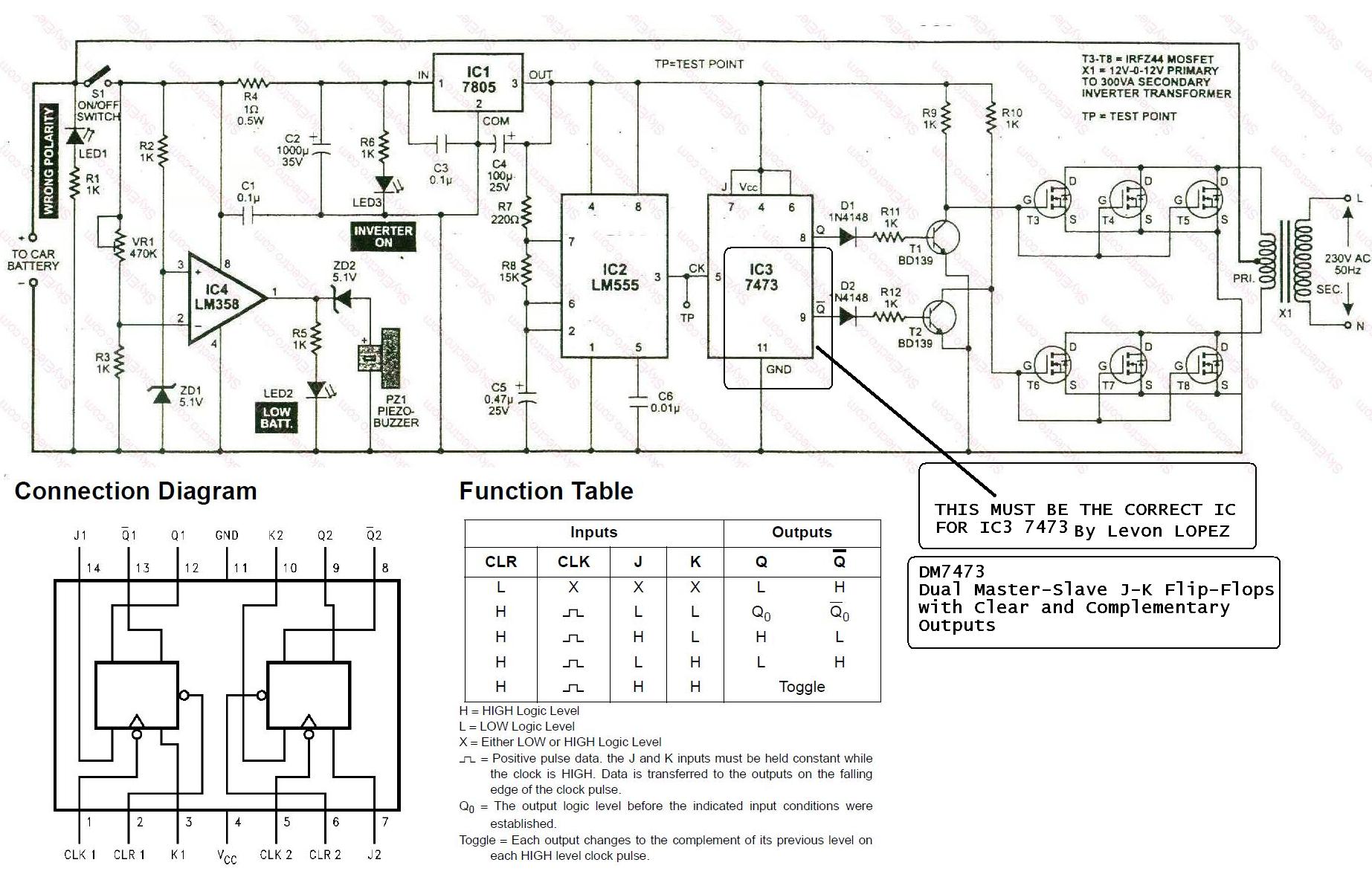
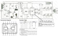
Please provide the explanation of the 12v dc to 220vac 100w inverter circuit. The dual master one.
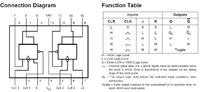
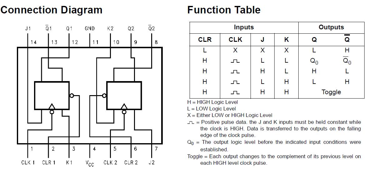
My email address is ;rtmakoenya@gmail.com
 

Control Circuit

555 Timer

its connected as astable multivibrater which produces the sqaure wave of 100Hz at the output pin 3.
R7, R8 and C5 determines the frequency.

7473
It acts a frequency divider.
With the input at pin 5 it produces 50Hz output at pin 8 and 9 180 degree out of phase. Which means at any instant if output at pin 8 is 0, at pin 9 it will be 1 and vice versa.

mosfets

when output at pin 8 is high the mosfet T3 to T5 conducts creating squarewave on the 1st half of the primary transformer.
When output at pin 9 is high the mosfet T6 to T8 conducts creating sqarewave on the other half of the cetertapped trasnformer.
It will conduct alternatly producing 240vac at the secondary coil of the tarnsformer.
 
  • Like
Reactions: hamedo

    hamedo

    Points: 2
    Helpful Answer Positive Rating
Hi all.
I have try to develop an inventer according to the following schematic...

When it was switched ON (I used automatic fuse switch 50 A) after 6 seconds the automatic switch was turned OFF by itself and heatsinks on 2N3055 transistors were a little warm and no output voltage at the secondary winding of transformer. 8O
I started to check parts and execution of schematic, and:
1. The frequency is about 50Hz on pins 10 and 11 of 4047, OK;
2. Also this frequency was after resistors 4.7K goes to LM358 inputs, OK;
3. Let say on pins 3 and 5 of LM358 this frequency also present, OK;
4. But then no frequency outgoes on pins 1 an 7 of LM358! I think it is not good, as far as I can understand the circuit the LM358 is in voltage follower mode and the frequensy has to be also present on output pins 1 and 7. But it doesn't, only voltage is about 0.6V present at bases of 2SC1061.
5. Furthermore no any works after LM358 outputs... Probably can be possible to add an series 10K resistors to pins 3 and 5 of LM358 connected to power supply and ground accordingly, to do some biasing of input signal. Or I am wrong and here should be other serious solutions...:cry:

Please can anybody help me to fix my problem with this inverter? Thank you in advance.

P.S. How can I check if the rest of transistors (2SC1061 and 2N3055) are OK and didn't damaged? So, how to check it in PCB by digital multimeter without desoldering of those parts?
 

Attachments

  • 500w_inverter_final_8724.png
    500w_inverter_final_8724.png
    201.1 KB · Views: 315

any body have a hand on SG3524 set for 50KHz osil?
 

The circute above is a square wave inverter,It work fine but it lack voltage control,the output voltage could be high then the battery is fully charged.
 

Re: 12vdc/220vac

How to use same circuit but with IC SG3524 ... Please can you give me the schematic ... thanks
 

Yes,if you use SG3524,you can control your output voltage as you want.

---------- Post added at 03:07 ---------- Previous post was at 02:55 ----------

 
dear friend how are you
kindly talk feel free tell me specific circuit what you want
 

qayyoum! i need circuit diagram of 3524 for 50Khz Sq wave for my project with PWM support. can you draw one for good sack?

---------- Post added at 19:35 ---------- Previous post was at 19:31 ----------

thanks kabriu! now i have to change only RD, RT & CT.
 

which kind circuit need mcu based are logicbase i meen analog circuit without controler tell me how much lod meen waat then we work on your project
 

The circute i post can be increase to a required power needed by increasing the size of transformer and mosfet.
 

which kind circuit need mcu based are logicbase i meen analog circuit without controler tell me how much lod meen waat then we work on your project

i need 3524 based analog circuit my requirements are:
Vcc= 10.5 to 14.5V @ 0.05UA and 50KHz Square
OR
Just calculate the value of RD, RT & CT in kabirue's diagram thanks.

---------- Post added at 11:56 ---------- Previous post was at 11:51 ----------

Kabriu! how about to use 3524 as PWM in my ATmel (https://www.edaboard.com/threads/57694/#post837897)???????
for increased PWM Fix. what do you think??
 

You can not generate SPWM with SG3524,In atmel a 32 or more sine pulse width modulation is compile to Hex file which represent you pure sine wave with the help of low pass filter,but your SG3524 is a regulating pulse width modul ation ic's so it is linear.
 

Hi, im new to this forum. Entered here after i found out some interesting conversations about inverter design (including this one). Im currently cramming to finish my design (and construction) of a pure sine inverter (12vdc-220vac) for school project. What i have so far is a constructed circuit for pwm generation (used sg3524 for this one). In a few days, i will be constructing the mosfet fullbridge using ir2110 as mosfet drivers but a friend of mine told me that the circuit has problems with deadtime. So we resorted to ir21834 because it has adjustable deadtime. Sadly, ir21834 is not available here so we have to stick to ir2110. Can anyone tell me about how to successfully generate 220vac from 12vdc using ir2110 driving a mosfet fullbridge?

---------- Post added at 23:01 ---------- Previous post was at 22:55 ----------

I will greatly appreciate replies about how to make the circuit work with high voltage because my current design (w/ ir2110) already works with seemingly perfect sine output in 15vdc input. But as the input voltage is increased, the mosfets heat up. This should not happen because my target dc input is 350v to chop it down and make 220 v sine output. I am currently considering of just stepping up the low voltage sine output using a transformer to get a final 220vac. But i have some negative thoughts with that method. Pls help me. This is a very important project and I have to finish it ASAP. THANKS.
 

Hi, are you using boost topology in your desinge? or you want to used 50Hz iron core transformer to step it up,and you complain of your mosfet are heating up if the voltage increases,can you tell me the type of mosfet you used for you desinge and how do you generate you pwm signal,you can upload your circute diagram if posible let see if their are error which make your inverter not to work properly.
 

Status
Not open for further replies.

Part and Inventory Search

Welcome to EDABoard.com

Sponsor

Back
Top