Continue to Site

Welcome to EDAboard.com

Welcome to our site! EDAboard.com is an international Electronics Discussion Forum focused on EDA software, circuits, schematics, books, theory, papers, asic, pld, 8051, DSP, Network, RF, Analog Design, PCB, Service Manuals... and a whole lot more! To participate you need to register. Registration is free. Click here to register now.

12v to 24v boost converter with 10-15a of current

Status
Not open for further replies.

aq_mishu

Full Member level 4
Full Member level 4
Joined
Jul 16, 2007
Messages
212
Helped
1
Reputation
2
Reaction score
1
Trophy points
1,298
Visit site
Activity points
3,402
Guys,
I need a boost converter that could deliver 10 to 15amps of current at 24v, constantly.

Now we can max get around 1a. Any ideas for such. Large current??

Mishu.
 

A discrete design using a boost control IC, 40A mosfet, 100V rated, 45V 30A schottky diode, suitable choke, o/p caps, input filtering, heatsinking...

:eek:) AC
 

Interleaving is definitely effective for >100W designs. Recently I designed a two phase 28V 400W boost using a LTC3787 controller, it worked well with efficiency >95%.
 

Interleaving is definitely effective for >100W designs. Recently I designed a two phase 28V 400W boost using a LTC3787 controller, it worked well with efficiency >95%.

Guys,
Forgot to tell you the big part, here in my country, i dont have any special ics. I can use uC for pwm and monitor for feedback. But above all, how should i achieve high current? Currently we are getting max 1.25 Amps at output.

Also, what is the meaning of interleaving here?? Cnfused...


Mishu.
 

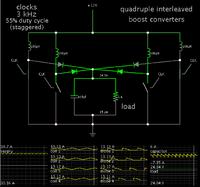
Here is a simplified concept of a quadruple interleaved boost converter.


The load receives 24V at 15A. (I made an assumption that the supply is 12V.)

It is about 85% efficient (in theory).

You would probably use mosfets for the switches.

You would need to join several capacitors, because there will be over 6 A going back and forth through them continually.

Dear sir, this looks interesting. Can you describe a bit more on this? Or some link? I googled and found nothing. It looks paralleling them, but why multiple cloks?? Its not like exact paralleling... So bit curious...

Mishu.
 

Status
Not open for further replies.

Similar threads

Part and Inventory Search

Welcome to EDABoard.com

Sponsor

Back
Top