mrinalmani
Advanced Member level 1
- Joined
- Oct 7, 2011
- Messages
- 463
- Helped
- 60
- Reputation
- 121
- Reaction score
- 58
- Trophy points
- 1,318
- Location
- Delhi, India
- Activity points
- 5,285
Hi
I am working on a 12V phase shifted full bridge connected to a 1:38 step-up transformer. The output of the transformer is rectified using SiC diode bridge. Fsw = 80KHz.
The MOSFET is PSMN2R030YLDX with 2mOhm resistance and maximum 2.5mOhm at Tj = 80C.
- When driving 40A current into the transformer, the power loss per FET is 8W (Measured using temperature rise, thermistor placed directly on each FET's metal tab).
- However the calculated loss is roughly 2W per FET. Approximately 1.5W Rds_on loss and another 500mW switching loss.
- There is no cross conduction or Miller turn-ON. I have checked.
- I measured the current waveform using a Mn-Zn ferrite current transformer with 1:50 ratio. I suppose the CT bandwidth should be at least 5MHz which should be sufficient to see the current characteristic.
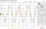
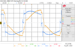
Here are some photos. Blue = Vds across low side FET. Yellow = Current through transformer primary measured using CT.

Figure-1: Current during FET turn-off.

Figure-2: Zoomed in view of Fet turn-off

Figure-3: FET turn-off at higher current. Notice bell-shaped voltage overshoot.
What could be the possible cause of 400% more power loss than calculated? Reverse recovery?
Also, a 22nF NP0 capacitor is in series with the transformer output (HV side) to compensate for leakege. This provides partial compensation, the net impedance seen by the bridge is still inductive.
Please share your views.
Thank you!
I am working on a 12V phase shifted full bridge connected to a 1:38 step-up transformer. The output of the transformer is rectified using SiC diode bridge. Fsw = 80KHz.
The MOSFET is PSMN2R030YLDX with 2mOhm resistance and maximum 2.5mOhm at Tj = 80C.
- When driving 40A current into the transformer, the power loss per FET is 8W (Measured using temperature rise, thermistor placed directly on each FET's metal tab).
- However the calculated loss is roughly 2W per FET. Approximately 1.5W Rds_on loss and another 500mW switching loss.
- There is no cross conduction or Miller turn-ON. I have checked.
- I measured the current waveform using a Mn-Zn ferrite current transformer with 1:50 ratio. I suppose the CT bandwidth should be at least 5MHz which should be sufficient to see the current characteristic.
Here are some photos. Blue = Vds across low side FET. Yellow = Current through transformer primary measured using CT.
Figure-1: Current during FET turn-off.
Figure-2: Zoomed in view of Fet turn-off
Figure-3: FET turn-off at higher current. Notice bell-shaped voltage overshoot.
What could be the possible cause of 400% more power loss than calculated? Reverse recovery?
Also, a 22nF NP0 capacitor is in series with the transformer output (HV side) to compensate for leakege. This provides partial compensation, the net impedance seen by the bridge is still inductive.
Please share your views.
Thank you!