Continue to Site
Follow along with the video below to see how to install our site as a web app on your home screen.
Note: This feature may not be available in some browsers.
Thanks,To upgrade for a uninterruptible power supply (UPS) need to add some rectifier (charger) - to convert AC power (from power grid) to DC power (to charge battery), supplementary controller - to control functions of rectifier (charger) to start or stop charging battery, how fast to change from grid power to battery power and for inverter when to start or stop power from battery to load, and some relays to change over time from grid power to battery power. In practice the off-line ups (the standard) switches to the batteries in 3 to 10 milliseconds, after the main power has been lost, but using the typical Inverter changes over in about 500 milliseconds. This gap is OK for household gadgets such as lights, fans, fridge, etc. but not OK for sensitive equipment.
That is a nice aproach for rapid switching.Thanks,
As i observe its an soft start inverter.
And no load current is only .4(400ma) from battery.
So if we keep it on every time there is no problem only 5watt load at mains power(grid power).
A seperate 12v charger and change over relays we needed.
Do you have idea about 10ms relay change over schematic.
Because 500m sec,enough time.
A computer can restart in mains failure with 500ms.
simply rememberHi,
There are a lot of Ready assembled kits available in the market plus you need a transformer of proper capacity according to the battery capacity. Simply pack this all in a separate box and thats it.
very well.Small computer supply for p3 or p4 is at least 350 watts. On most of them current output is written on a sticker. !2v at 10a is common. You have to modify circuit arround lm431 to increse voltage.
**broken link removed**
13.8 V / 15 A from a PC Power Supply
PC Power Supply
Converting PC power supply to power 12v charger? - RC Groups
yes battery,s negtive and dc 300v ,s negtive is common.I have seen many inverters, battery and output is already isolated. Are you sure yours is not?
yes nica idea.The common point can be seperated but there is need for 12v supply for out put circuit. This can be achieved by winding 3 turns of #28swg enemel wire on existing ferrite transformer. After rectification and filtering and using series regulator 7812.
There is always some space in ferrite transformer to push through some extra turns.
Yes you are right.Small computer supply for p3 or p4 is at least 350 watts. On most of them current output is written on a sticker. !2v at 10a is common. You have to modify circuit arround lm431 to increse voltage.
**broken link removed**
13.8 V / 15 A from a PC Power Supply
PC Power Supply
Converting PC power supply to power 12v charger? - RC Groups

hello,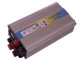
Attached pitcure is a 12v dc to 220v ac inverter.

Of course i already have control pc smps as a 12volt battery charger,with additional Lm358 and pc817 circuit.A charge monitor circuit can control output voltage by replacing the trimmer for setting output voltage and hense current. You can check current control function manually by providing input to pc817 (0 to 6mA) t hrough a variable resistor. Current monitor circuit using an operational amplifier can provide control signal for pc817 optocoupler.