ericlouie1
Newbie level 3
I was looking at another post for my exact same application, but the schematics were a little vague, just wanted some opinions on my take on it.
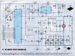
I am building a 12vdc PWM speed controller, single direction. The input voltage on the system will be around 13.3 volts. The estimated current draw of the motor is between 25 and 35 amps, giving me a worst cast power depand of around 500 watts. A bypass will be included on the circuit to allow for full speed of the motor at the push of a button, to clear chunks and jams. Either fuse or breaker protection is needed as well, 10amps for the PWM, and 40 for the motor.
Took me a little bit to understand the concept of a mosfet and the PWM system but i think I have a pretty good grasp on it now.
I'm not exactly sure if all my component selections are correct.
I am shooting for a frequency of 10K, seems to be the magic number for noise and whatnot.
I get this using values of .096uf for the caps and 1.5K POT.
Do i use this value for the rest of the capacitors in the circuit, or will .01 uf caps be sufficient for this task?
Not exactly sure what the purpose of the 10k resistor for r2.....
For the mosfets i was thinking about two of three of these, hooked up the a heat sink and possible fan- STP200nf04
(wont let me post link)
40v source breakdown, 120 amps, 310 watts
For the timer, either a LM555 or a TLC555, the latter has a slightly higher power dissipation and temperature rating.
Gotta post more to do pic or links, drats.
---------- Post added at 05:04 ---------- Previous post was at 04:45 ----------
Probally going to stuff this into some kind of project box, just gotta figure out what size i will need with the heatsinks and fan and whatnot.