boylesg
Advanced Member level 4
- Joined
- Jul 15, 2012
- Messages
- 1,023
- Helped
- 5
- Reputation
- 10
- Reaction score
- 6
- Trophy points
- 1,318
- Location
- Epping, Victoria, Australia
- Activity points
- 11,697
http://www.talkingelectronics.com/projects/100 IC Circuits/1-100_IC-Ccts.html#20
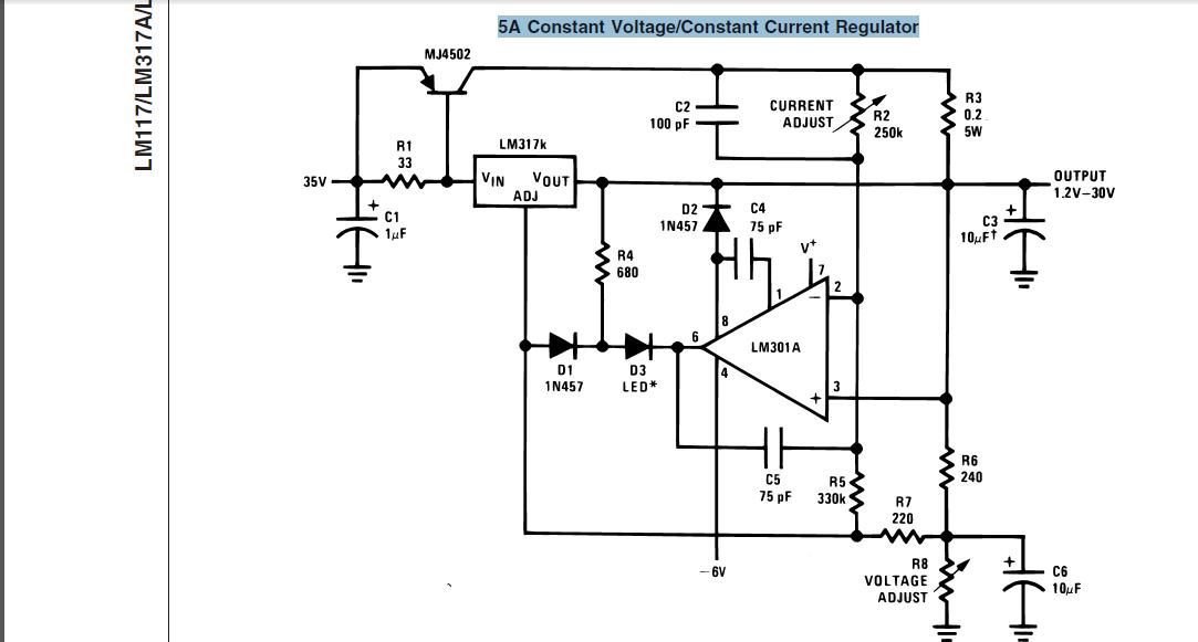
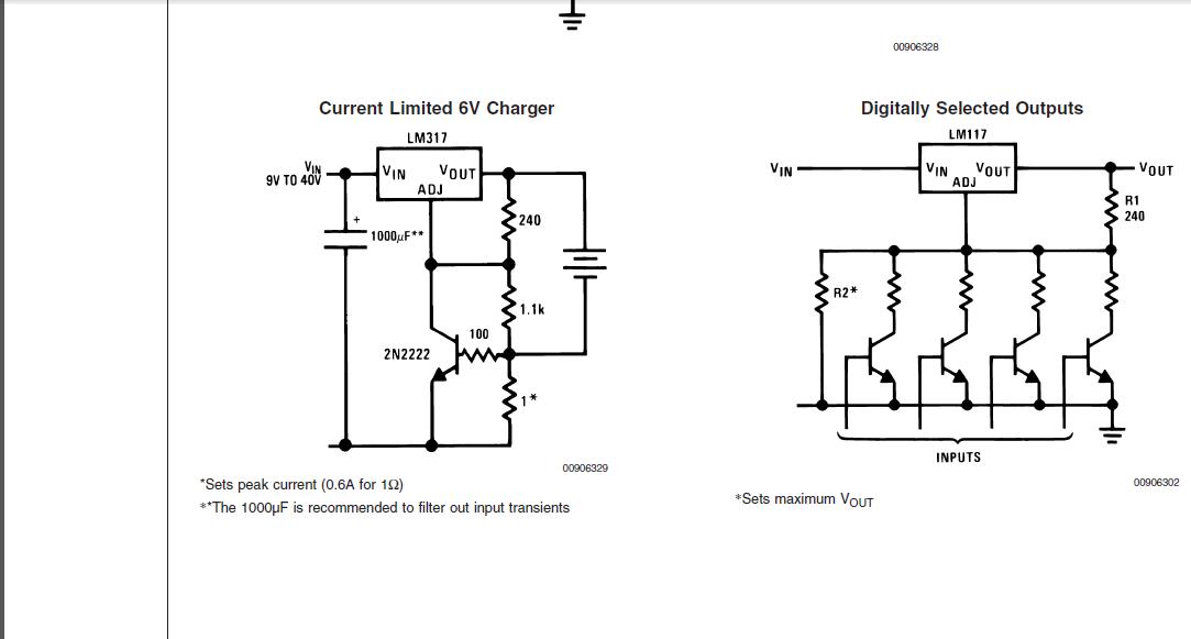
Could some one explain to me why you would put the transistor on common pin of the voltage regulator as opposed to the output line, i.e. like a light switch.
I do not have enough of an understanding of how a linear voltage regulator works.
Could some one explain to me why you would put the transistor on common pin of the voltage regulator as opposed to the output line, i.e. like a light switch.
I do not have enough of an understanding of how a linear voltage regulator works.
")