Continue to Site

Welcome to EDAboard.com

Welcome to our site! EDAboard.com is an international Electronics Discussion Forum focused on EDA software, circuits, schematics, books, theory, papers, asic, pld, 8051, DSP, Network, RF, Analog Design, PCB, Service Manuals... and a whole lot more! To participate you need to register. Registration is free. Click here to register now.

12V 1500W inverter crashes at 450W

Status
Not open for further replies.

poseidon22

Newbie
Joined
Feb 5, 2023
Messages
3
Helped
0
Reputation
0
Reaction score
0
Trophy points
1
Activity points
39
I have an old sine wave inverter 12V 1500W, unfortunately the control of the MOSFETs no longer works. That's why I built a circuit with EGS002 as shown in the EGS002 data sheet. There 4 IRF3205 are controlled.
My inverter has 4 groups of 9 IRF3205s each, a total of 36 pieces. I controlled each group as a single MOSFET with 1 piece 4.7Ω resistor and 1 piece diode IN4148. As a pull-down resistor I used 7.5K for each group.
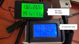
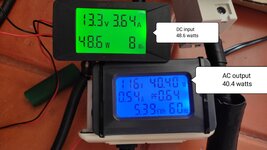
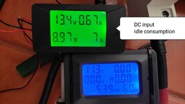
The inverter works with this circuit. However, if it is loaded with more than 450 watts, the voltage collapses. Can someone give me information about what is wrong with my circuit. Do I have to drive each individual transistor with a 4.7Ω resistor + diode IN4148 and a pull-down resistor?
 

Attachments

  • EGS002 EG8010.pdf
    463.8 KB · Views: 124

Driving parallel 9x3205 fast requires stronger gate driver than IR2110 used in EGS002 module. Reducing the effectiv parallel gate series resistance is no option, need booster driver, e.g. complementary bjt source follower.

What's the exact observation, just reversible voltage collapsing with higher load or real "crash"? How about the current sense implemented in the applivcation circuit? Did you omit it, keep it or adjusted to the expectable current level? Did you observe the 12 V input voltage with rising load? How is the operation at moderate load, do you see excessive transistor heating?
 

Are you measuring the input line voltage meanwhile?
450W out at (say) 80% eff would mean about 45A of
12VDC input current. There's a lot of batteries which
won't deliver that, new. Along with most bench power
supplies.
 

Yes, also, you cant simply drive parallel TO220 FETs in parallel...they each need there own driver......otherwise you get high frequency oscillations between the gates. Take apart any cheap PSU....they woudl make it cheaper by paralelling the FETs with one driver, but they dont do this...they have a driver per fet.
 

What's the exact observation, just reversible voltage collapsing with higher load or real "crash"? How about the current sense implemented in the applivcation circuit? Did you omit it, keep it or adjusted to the expectable current level? Did you observe the 12 V input voltage with rising load? How is the operation at moderate load, do you see excessive transistor heating?
Thanks to all for the responses,
On closer inspection I would say it is a voltage dip at higher load. The EGS002 shuts down and restarts automatically as seen in the video.
The current measurement pin 1 I put on the minus pole and thus out of service.
Yes, I have observed the voltage. It is not seriously broken, I will test it again.
My battery is a LiFePO4 13.2V 560Ah. It is very powerful.
The device with which I generate the load on the inverter is a battery charger with 12V 40A. The output of the battery charger I connect to the battery so only the power loss of the inverter and the battery charger is applied by the battery.
With moderate load everything runs well. There is no excessive transistor heating The current consumption at idle is 10Watt

As an attachment to this message I have the schematic of the inverter. It is an inverter and charger in one the charging function I do not need. I charge the battery with solar panels
 

Attachments

  • PM-1500SL.pdf
    141.4 KB · Views: 136

There appears to be no step up transformer on the schematic .... (?)
Yes I can't find a transformer on the schematic either. But in my device is a thick toroidal transformer he has 4 connections 2 times to X1 and 2 times to X2
I measured the input and output power today. The pictures are attached

Question
Is it possibly better to re-solder the 10K resistors on each MOSFET and use 4.7Ω resistors on each MOSFET instead of the 20R resistors
Other question what are the capacitors 103 useful for on each MOSFET?
 

Attachments

  • IMG_20230206_133954 351W.jpg
    IMG_20230206_133954 351W.jpg
    716.8 KB · Views: 72
  • IMG_20230206_133436 48W.jpg
    IMG_20230206_133436 48W.jpg
    787.8 KB · Views: 76
  • IMG_20230206_132849 idle.jpg
    IMG_20230206_132849 idle.jpg
    2.7 MB · Views: 95

4.7Ω resistors on each MOSFET instead of the 20R resistors
Depends if your gate driver is powerful enough to drive the gates high with 4R7's....look at the internal resistance of the gate driver....then look at the gate drive vcc.....then do ohms law and see how much gate drive current you get for each fet.
iT looks like you are getting away with pllel FETs because your h bridge voltage is low, and voltage only goes high at output of your low frequency transformer.
The 10n caps will do very little for you......they will just discharge unwanted spikes of current thru the fet when it switches on. The 10n caps like that are usually to reduce turn off switching loss...but your voltage is so low that you neednt worry.
If you want to help EMC you could change them for RC's
 

Status
Not open for further replies.

Similar threads

Part and Inventory Search

Welcome to EDABoard.com

Sponsor

Back
Top