Continue to Site

Welcome to EDAboard.com

Welcome to our site! EDAboard.com is an international Electronics Discussion Forum focused on EDA software, circuits, schematics, books, theory, papers, asic, pld, 8051, DSP, Network, RF, Analog Design, PCB, Service Manuals... and a whole lot more! To participate you need to register. Registration is free. Click here to register now.

120V Mains measurement circuit, would this circuit pass safety inspection / approval

Status
Not open for further replies.

Jester

Full Member level 6
Joined
Aug 18, 2012
Messages
377
Helped
7
Reputation
14
Reaction score
7
Trophy points
1,298
Location
.
Activity points
4,754
Hi,

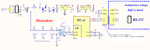
Is there any obvious reasons why this circuit would not get approved (safety wise)?

Assume the following:
- The fuse, MOV and C31 are safety approved parts.
- Digital Isolator is approved https://www.silabs.com/Support Documents/TechnicalDocs/Si861x-2x.pdf
- Enclosed in approved plastic enclosure
- Power supply on low voltage side is 5Vdc and approved
- Creepage between hazardous and low voltage side are adequate
- Circuit in hazardous domain requires less than 20ma

Should I be using a "X" cap or a "Y" cap for this application?

Choice for D2, D3, the peak current can be I believe 1.7A (power applied at peak of sinewave), however average current is quite low, Suggestions on a more suitable diode for D2, D3?

OPA4180 is rail to rail (output range includes -rail and within 1.5V of positive rail) https://www.ti.com/lit/ds/symlink/opa4180.pdf


Please feel free to critique in any way.
 

Attachments

  • Safety.png
    Safety.png
    77.4 KB · Views: 106

What happens if one of those resistors into the opamp fails shorted?
 

Shorted resistors are highly unlikely. As there are three sharing the voltage equally their rating should be adequate. Provided all the 'live' side was finger proof I would be happy to say it was electrically safe.

Brian.
 

Not related to safety, but the OP circuit is missing a positive bias to measure AC voltage.
 

I found this part that seems ideal: **broken link removed**

****however the device comes in a SOT-89 package, there is only 0.5mm (20mils) between the input and output pads that would have > 160V!

IPC-2221 --> 1.25mm (50mils) minimum

Does not seem safe?

Also available in TO-252
 
Last edited:

FvM, I spotted that too but didn't have the op-amp data sheet to see exactly what it does. One chain of the dropper resistors is essentially redundant at the moment as it connects to the same ground as the amp. Some bias is needed unless the intention is to detect zero crossing but if that is the case, there are easier ways to do it.

I'm not sure what the issue is with the high voltage across the regulator. They should only have 2V and 4V across them. If the input components have failed and allowed high voltage to reach them the circuit would already have catastrophic failure and either be fried open circuit or the fuse blown. Either way, the output side should still be safely isolated.

The only other point I would make is that R5 should be a safety rated resistor, it should run almost cold but ideally you would use a fusible type in case of prolonged overheating in it's environment or a failure that increases the current but still below F2 rating, for example one of the diodes going short circuit.

Brian.
 

I appreciate the advice, a few more comments and questions:

Comments:
1) I moved the Zener Z4 to the other side of D2 eliminating one of the 4007's, I don't see any downside, please correct me if I'm wrong?
2) Fixed bias on op amp (2v5 @ RA6A)
3) R5 is fusible / flameproof https://www.digikey.ca/product-detail/en/FRM1WSJT-52-100R/100BATB-ND/2208183

Question regarding protection of U13:
The protection diodes in U13 are rated for 10ma, so 90k * 10ma = 900V max protection?
Do you think this would survive a 61000-4 Fast transient test 4kV, 2kV? or should I add beefier protection diodes (BAS-04) or similar at input to opamp?


Updated schematic:
 

Attachments

  • ai.jpg
    ai.jpg
    126.2 KB · Views: 77

U13 pin 3 will never have more than 2.5V on it so no worries there. I'm not sure you really gain anything by differential measurement when one side of the signal is 'ground' reference anyway. You could consider removing R19 and R20 from their present position and adding one or both of them in series with R17 or R18.

The high voltage protection isn't helped by adding extra diodes. The internal diodes in the op-amp will clamp the voltage across the inputs and turn any excess curent to heat, for short duration that would be minimal. There is an unlikely but possible scenario that a spike could be conducted from the inputs to the supply pins and then appear across the (presumably) 5V rail. You could add a zener diode of 5.1V or 5.6V across the 5V rails to absorb it if you wanted.

I would be inclined to move the measurement point to after R5 rather than before it. At the moment, if R5 'fuses' it leaves the op-amp with voltage at it's input but no supply voltage.

The important thing about the diodes is they should allow current to flow in both directions through C31. If you removed one or the other it would simply charge to some DC potential and the circuit would fail to operate. The new arrangement should work but may leave some residual DC on the capacitor and of course drops the available voltage to the regulator by about 0.6V. If this isn't a cost critical design, I would leave the diodes as they were.

Brian.
 

Status
Not open for further replies.

Part and Inventory Search

Welcome to EDABoard.com

Sponsor

Back
Top