Continue to Site

Welcome to EDAboard.com

Welcome to our site! EDAboard.com is an international Electronics Discussion Forum focused on EDA software, circuits, schematics, books, theory, papers, asic, pld, 8051, DSP, Network, RF, Analog Design, PCB, Service Manuals... and a whole lot more! To participate you need to register. Registration is free. Click here to register now.

12 volt dc delay on timer

Status
Not open for further replies.

Nishon

Junior Member level 1
Joined
Oct 4, 2012
Messages
17
Helped
0
Reputation
0
Reaction score
0
Trophy points
1,281
Activity points
1,402
Hey guys!
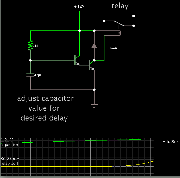
I need to build a 12 volt dc delay on timer.on application of supply voltage,the timing cycle should start and after a 5 second delay the output should activate a 6 volt or 12 volt relay.I would really appreciate it if somebody could help with a circuit diagram preferably using the 555 ic as a timer.
Thanks guys
Nishon Premlall
(South Africa)
 

can you rephrase the problem?
 

I need a 12v dc delay on timer.when you apply 12v dc to the timer,it needs to switch an external relay after 5 seconds.
 

Using NE555 pls note ...............draw the cct diagram as you're reading....... thanks( 555 timer pin1.....pin8..)loop pin2 to pin6,loop pin4 to pin8.pin1 to negative.pin3 o/p.connect capacitor Cx(10uf 25v) pin8( ) and pin6(-) .connect variable resistor Rx 2.4megaohms and diode In4007 to pin1 and pin2.connect diode 4007 from pin2 to pin3 output.connect 12v zeaner diode from pin1 to pin4.from 12v dc source connect two resistors 2.2k and 10k ,2.2k to pin1 and 1k to pin 4.connect pin3 to base of TIP41, collector of tip41 to th relay coil than 12v to relay coil . connect diode b/w the relay coil.Finally conect your load to normally open and common the relay.Time to switch on depend on value of Cx or Rx.I normall use this for automatic transfer switch ,inverter etc
 

I need a 12v dc delay on timer.when you apply 12v dc to the timer,it needs to switch an external relay after 5 seconds.
try:
**broken link removed**


kyrietec, could you draw your circuit as the description is not clear ...

:wink:
IanP
 

Thanks guys,I really appreciate the help.krietec I'm going to try and draw your circuit,thanks.

- - - Updated - - -

Krietec please post a diagram,I tried putting your circuit diagram to paper but it just doesn't go.will really appreciate if you could do so,thanks.
 

The transistor is npn connect the emitter to ground .Guy I'will send you the cct diagran .
 

Ok looking forward to it krietec
 

Krietec I'm still waiting for your diagram buddy:sad:
 

Although a 555 IC is fine for creating several seconds delay, there may be a momentary 'on' at power-up. It may or may not affect operation of the relay.

The circuit below is not too different from what happens in a 555. In any case, something like it can be used in case you don't have a 555 handy.


Status
Not open for further replies.

Part and Inventory Search

Welcome to EDABoard.com

Sponsor

Back
Top