Continue to Site

Welcome to EDAboard.com

Welcome to our site! EDAboard.com is an international Electronics Discussion Forum focused on EDA software, circuits, schematics, books, theory, papers, asic, pld, 8051, DSP, Network, RF, Analog Design, PCB, Service Manuals... and a whole lot more! To participate you need to register. Registration is free. Click here to register now.

10a H-bridge not fully working

Status
Not open for further replies.

nin82

Newbie level 5
Joined
Sep 18, 2010
Messages
9
Helped
0
Reputation
0
Reaction score
0
Trophy points
1,281
Activity points
1,341
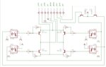
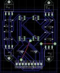
Hi, I decided to build this H-bridge to drive a power window motor which is rate at 12v 8A and it works to the point that it will switch the motor's direction BUT if I put a load (i.e hold it with my finger tips to make it stop rotating) on the motor the tips(142 & 147) will just heat up and the motor wont move at all i first thought the lines on the PCB were to thin but when i hook the tips by them self's with thicker wire i get the same result. its almost as if the tip142 and 147 were not designed for high currents also i hooked my psu (the yellow line and black 12v 20A) to thin telephone wire and then to the power window motor and it worked like it should. what am i doing wrong?? are the resistors to small??? they are 1/2watt. I am running out of ideas.

I Have attached the eagle files brd and sch if its of any help

thanks for reading8-O
 

Attachments

  • untitled.zip
    20.8 KB · Views: 87
  • sch.JPG
    sch.JPG
    46.9 KB · Views: 139
  • brd.JPG
    brd.JPG
    55.9 KB · Views: 115
Last edited:

I've never tried what your doing but understand how motors work, it sound's like your not driving the transistors hard enough. What does the voltage drop down to when you place your fingers on the motor. Plus how are you controling the transistor's, What's the bse voltage drop to at the same time

sorry cant be more of an help
 
  • Like
Reactions: nin82

    nin82

    Points: 2
    Helpful Answer Positive Rating
hey thanks for the help wizpic! any help is better than no help at all. the voltage drops to zero. if i read the voltage that goes to the motor i get 11.2v with out the motor connected once its in place it drops to 8.9V and if i try to stop the motor i drops gradually until it reaches zero and at the same time the tips get hot.

how can i drive the tips hard enough? i have used smaller resistors and nothing happens or i get smaller voltages and thus a weaker motor and the tips get hot. on the other hand if i use bigger ones it wont run at all. do i need some 1 watt resistors instead_? or mabe even bigger ones?
 

I think the problem could be the opto's not supplying enough drive current for the tip's.
Did a quicj serach and came up
http://www.pocketmagic.net/wp-content/uploads/2009/03/hbridge-radu1.jpg
**broken link removed**
Then I came across this which looks simular to yours
**broken link removed**

I persume your tip's are on a good size heat sink and the motor is rated less than 10amps
 
  • Like
Reactions: nin82

    nin82

    Points: 2
    Helpful Answer Positive Rating
Your Darlington transistors have a Vce saturation voltage of
2v when Ib=10 mA and Ic=5A
3v when Ib=40 mA and Ic=10A

For the output current that you want to use you should expect at least 2v+2v drop on the two diagonal transistors, 12v-4v=8v output or lower when the current increases.

Alex

---------- Post added at 01:36 ---------- Previous post was at 01:26 ----------

You should also add resistors to the optocoupler diodes to limit the current, these diodes have a forward voltage of about 1.5v
 
thanx alex so my problem is that i need a bigger psu? 24v maybe? i didnt add the resistors to the optos because I am using the pin output of a Uc to exite them, you think i should still use them anyways?

---------- Post added at 11:27 ---------- Previous post was at 11:19 ----------

thanx once again mate yes wizpic the motor is 8A 12v and no the tips arent attached to any heat sink yet, i thought i should first try them and if it got hot enough i would **** some aluminum bricks xD yes i know is not the best practice. i forgot to mention that i have try to excite the tips directly with out the optos and still get the same result
 

Yes a resistor should be used to limit the diode current, even if the mcu can't provide enough current to damage the diode you still stress the mcu output because it tries to provide as much current as possible and depending on the mcu this can be above limits (of the mcu specification).

Using 24v will not solve your problem because then you need to use a feedback system to limit the current of the motor, you can't apply 18v to a 12v motor unless you use some pwm.
If you apply a power supply of about 16-17v to the bridge then it should be ok because you would get about 12v to the motor.
A mosfet bridge would be the suggested method in my opinion, you will get a very low voltage drop and the heat on the active devices wil be very low too.

Alex
 
  • Like
Reactions: nin82

    nin82

    Points: 2
    Helpful Answer Positive Rating
thank you very much Alex. anything else you think is wrong with the design?
 

The 1k resistor in the base of the tip transistors limits the base current to about 10mA assuming that the optocoupler can provide that much, if you increase this current to 30-40mA you will get better results (lower voltage drop) in the output.

The graph of your optocouples figure 6 page 4 ( **broken link removed** ) shows that the diode current needs to be about the same as the collector output so you should set the diode resistor accordingly (30mA to the diode to get 30mA output current).

You can easily measure the base current by measuring the voltage drop on the TIP base resistor when the optocoupler transistor is on , then using that voltage drop a simple V/R (R is the base resistor of course) will show how much current flows through the resistor to the base.

You can also take a look BJT H-bridge -- Chuck's Robotics Notebook for a similar design

Alex
 

anything else you think is wrong with the design?
I would suggest this steps:
- correct the obvious flaws in the optocoupler drive circuit
- try again
At present, it's impossible to say if the optocouplers will be immidiatly damaged by overcurrent, or if one of the pathes possibly won't source sufficient current due to the unsuitable parallel circuit of LEDs.
The other point to mention is this: If you observe incorrect operation of the circuit, why don't you start making some measurements on your own? The 1k base resistors are a perfect place to determine the drive current of each output transistor. You also didn't report a measurement of the 12V supply input in loaded case.
 
  • Like
Reactions: nin82

    nin82

    Points: 2
    Helpful Answer Positive Rating
thanks FvM the voltage measurement of the of the 12v input while loaded in the psu was of 11.56v thanks for the help
 

Status
Not open for further replies.

Part and Inventory Search

Welcome to EDABoard.com

Sponsor

Back
Top